Some mechanical solutions required
| MANUAL TRIM panel Some mechanical solutions required |
 |
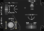
The MANUAL TRIM panel has just a few controls and indicators, but its simplicity is deceiving! There
is one "flat-top" switch, 3 potmeters and two small 180° rotation needle pointer indicators. Easy, you'd say. Yes, as far as that
2-position switch and the YAW TRIM knob goes. However, in the real F-16 MANUAL TRIM
panel, the ROLL TRIM knob and its associated needle indicator is one unit. Same goes for the
PITCH TRIM knob and its associated needle indicator. When you rotate the trim knob, the needle indicator
is also moved via some gears inside the unit.
Further, on the Side Stick is a round button that can be moved in four directions, effectively roll and pitch trimming the
aircraft. When using the Side Stick, the knob and needle indicator move! So, there must also be some form of a servo mechanism
involved.
All that is mechanically way too complicated for me, so I was thinking of a solution that I can build.
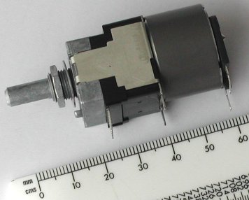
So to summarize, what do we have for each trim knob?
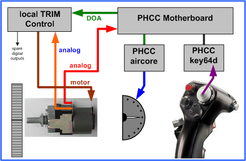 To keep things simple, I decided to build a separate "PHCC daughterboard" to control the two motor potmeters. This is really
a simple design, as it only needs to read the analog potmeter setting and drive the motor. I am using the fact that this
motor potmeter actually has two potmeters on the motor shaft, and that I already have the PHCC aircore daughterboard.
The extra cost for a "local controller" for the motor potmeters is just 5 Euro. All other components would be needed anyway.
Besides, with the local electronics, the wiring to the MANUAL TRIM panel is kept simpler.
To keep things simple, I decided to build a separate "PHCC daughterboard" to control the two motor potmeters. This is really
a simple design, as it only needs to read the analog potmeter setting and drive the motor. I am using the fact that this
motor potmeter actually has two potmeters on the motor shaft, and that I already have the PHCC aircore daughterboard.
The extra cost for a "local controller" for the motor potmeters is just 5 Euro. All other components would be needed anyway.
Besides, with the local electronics, the wiring to the MANUAL TRIM panel is kept simpler.Initially, I planned to use a so-called "H bridge" to control the motor. Using an H bridge, you can control the current flow direction through the motor, making it rotate clockwise or counter-clockwise. However, this is just a small motor and the design of an H bridge using MOSFETs is not that simple, especially the "high-side switching" section. I do not see any reason why not to use a simple relay to reverse the power supply polarity. Likewise, you can use a relay to switch the motor on and off, driving the motor directly from a power supply. However, I like to keep the possibility in my design to use a PWM signal to lower the rotation speed of the motor. Thus, switching the motor on and off will be done with one MOSFET. The PWM is just a matter of switching on and off very fast!
As you can see looking at the MANUAL TRIM panel, the motor potmeter will be at the same location
as the aircore motor. As the aircore motor has a short thin shaft to drive the needle directly, the aircore is mounted on a
small piece of circuit board directly on the backplate. Thus, the motor potmeter has to be installed at some distance from the
panel, above the aircore.
The trim knob is mounted on a shaft using a 50 teeth gear. The diameter of the 50 teeth gear is sufficient to mount the trim knob
on the gear using three M2 screws. This shaft is driven by a 40 teeth gear. On the motor shaft is a 22 teeth gear. To obtain
the required distance from the backplate (to create space for the aircores, an additional intermediate 40 teeth gear is used.
The ratio is 22/40, which is good, because the motor potmeter can rotate 300°, and the trim knob on the panel seems to have a
rotation range of approximately 120° - 150°. Thus, the trim knob range is translated to almost the full rotation range of the
potmeter.
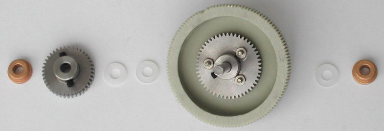
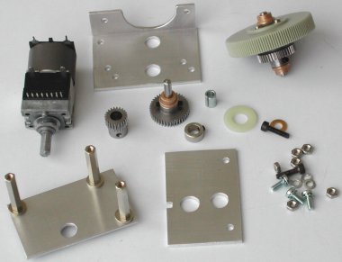 At the left you see the parts needed to build the trim wheel. construction for one knob. The trim wheel assembly consists of two
aluminum plates and one L-shaped aluminum bracket. The two plates are 37 mm x 58 mm, the L-shaped bracket is 20 x 40 mm, 58 mm
long. The trim wheel is mounted one a 50 teeth gear (sufficient diameter, the gear is only used to mount the trim wheel on the
shaft). On this shaft is a 40 teeth gear mounted. The diameter of the shaft is 4 mm. The shaft is held between the L-shaped
bracket and one metal plate using collar type brass slide bushings (which are oiled). The collar of these bushings "locks" the
shaft between the bracket and the metal plate.
The "intermediate" 40 teeth wheel is mounted on the L-shaped bracket, also using a collar type brass bushing. The pictures shows
a metal bushing with an inner diameter of 4 mm to fit on tha shaft and an outer diameter of 6 mm to fit on a 6 mm ring with a
setscrew. However, I found some 4 mm rings with a setscrew, so the bushing and 6 mm ring are replaced with the 4 mm ring (which
is better!)
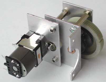
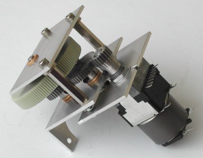
The other metal plate is mounted on the opposite side of the L-shaped bracket using two M3 screws. The motor potmeter is mounted
on this metal plate. The complete assembly is mounted on the backplate of the MANUAL TRIM panel
with the L-shaped bracket using two M3 screws.
 |
 |
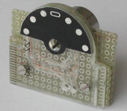
The two "half moon" openings in the MANUAL TRIM panel are for the trim indicator. Mike's panel comes with the following parts for each needle indicator (going from the front panel side to the backplate side).
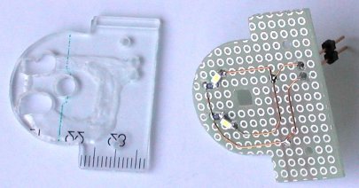 The first "module" realizes the backlight of the indicator dial. On a small piece of circuit board are two SMD LEDs soldered
with their series resistors. Against the circuit board is a piece of a ruler (!) mounted. The thickness of the ruler should be a
bit more than the height of the LEDs, but should not be too thick, otherwise the axis of the aircore motor is not long enough.
I drilled and filed openings in the ruler for the LEDs and resistors and cut grooves for the wires, so that the circuit board
can be mounted flat against the ruler. The ruler is mounted against the backplate and is also the surface onto which the
indicator dial is glued. The ruler makes a smooth surface for the indicator dial, because putting the indicator dial just on
top of the two SMD LEDs would not be a "vibration-proof" construction. With this construction, the indicator dial is a bit
further back from the front panel. Remember, the total height is limited, because of the length of the shaft of the aircore,
but some play is possible with the length of the flexible tube. If the rear side of indicator dial would be against the
backplate, the space for the needle between the indicator dial and the front glass is very small.
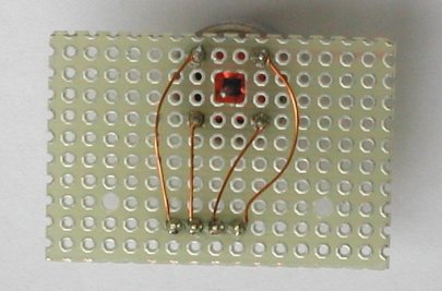 The second "module" is a piece of circuit board on which the aircore motor is soldered. Before you solder
the aircore motor on the circuit board, you must make sure that the "middle position" of the rotation range is at the zero
position of the indicator dial. The aircore motor is not a real motor in the sense that you can make it spin round and round.
In the 360° rotation, there is a small "dead zone". If that "dead zone" in within the indicator range, you will curse and pull
your hair ... and pray that you can remove the aircore from the board without destroying it.
The circuit board with the aircore motor is mounted against the SMD LED circuit board. If you cut the "LED board" and "motor
board" with the opening for the axis in such a way that all the soldering holes in both boards align, you have to cut off just
1 mm of the pins of the aircore, because the rest of the length of the pins can go into the holes of the "LED board". This way,
the two circuit boards, the ruler and the indicator dial make a compact and strong unit that can be mounted on the backplate
using two M2 screws. As the four soldering joints for the aircore need some space, I have cut a bit of the board material on the
LED board away with a drill. Do that manually, not with the power tool! A ring on the M2 screws between the LED board and the
aircore motor board gives the needed space for the four connection wires of the aircore motor.
And these are all parts to construct one aircore TRIM indicator.
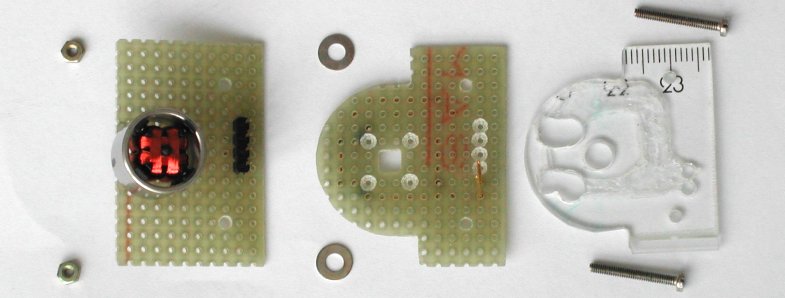
The check that everything fits (it should), put the two M2 screws through the holes in the "ruler plate". Then put the LED board
on the screws. Check that the ruler and the board fit perfect against each other, otherwise it will be difficult to get the axis
of the aircore perpendicular to the trim dial. As you can see, I used a 3.5 mm drill to manually remove some of the board material
so that the solder joints of the aircore and the 4-pin header are not in the way to mount the aircore board also perfectly fitting
against the LED board. There is some tolerance allowed, because between the LED board and the aircore board are rings to make some
space for the aircore wires to the 4-pin header. The aircore board is the last part, and two M2 screws holds everyting together.
As a final step the trim dial is glued onto the ruler surface with a small piece of double-sided adhesive tape.
Now disassemble the contraption ... this was just the check that everything fits the way it should. Using the "ruler plate" with
the glued trim dial, you can now determine where you must drill two 2 mm holes in the backplate. For good orientation, mount the
MANUAL TRIM panel with the correct screws onto the backplate. If possible, mount the trim wheel
assembly also on the backplate (of course before you mount the panel). Now you can put the "ruler plate" on the rear side of
the backplate and visually align the trim dial in the correct position. Mark the two holes in the "ruler plate" with a pencil on
the backplate. Remove the MANUAL TRIM panel (and trim wheel assembly) and drill the two 2 mm holes.
Once again, put everything back together!
I assembled countless times sub-assemblies and partially completed items to see if all fits, and get ideas how to proceed.
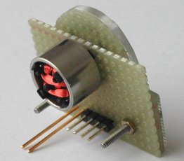
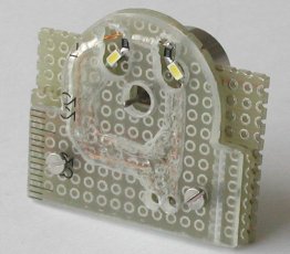
Now, put the indicator glass in the MANUAL TRIM panel, and carefully put the trim indicator assembly
on the backplate. Check that the end of the axis of the aircore does not touch the indicator glass. If it does, simply put
extra rings on the M2 screws between the LED and aircore board. I only needed one ring which is required to get the distance for
the wires to the aircore.
 |
 |
 |
Again, remove the trim indicator assembly, and then remove the indicator glass. Install the trim indicator assembly again onto the
backplate. Connect the 4 pins of the aircore to the PHCC aircore daughterboard (or whatever hardware you use to control aircores).
You have to control the aircore axis to determine the correct position of the needle. You can choose two different methods.
The indicator needle is mounted on the aircore axis with a small piece of tube. The inner diameter fits snug on the aircore axis
and the hole in the indicator needle fits snug on the outer diameter. Hold the indicator needle with tweezers on the axis so that
the end of the axis is through the indicator needle just at the surface of the needle to determine the length of the tube. As the
aircore itself is at some distance, the length of the tube is not critical, but excessive length will make it more difficult to
push the tube with the needle onto the axis.
Before you can put the needle on the aircore axis you have to paint it. First, apply a thin layer of white paint on the needle
pointer part (thus, no white paint on the round part for the shaft. This side (with white paint) faces towards the indicator dial.
The round part for the axis must remain transparant, so that light (from the dial backlight LEDs) can illuminate the needle
pointer. To block that light, the round part of the needle pointer is painted black on the top, the view side facing towards the
indicator glass. This way, only the pointer part of the needle is illuminated.
After the paint has dried, put the cut-to-length piece of tube in the shaft opening of the needle pointer. The tube with needle pointer fits snug on the shaft of the aircore. Note that, once the needle pointer is mounted on the shaft, you cannot remove the aircore or LED module without pulling the indicator needle & tube from the aircore axis. The aircore is a delicate "toy" ...
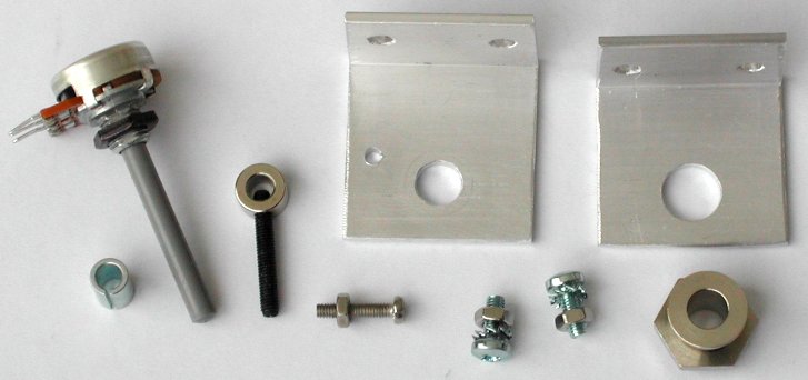
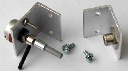
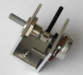
The YAW trim potmeter is a bit special, if compared to a normal potmeter. A normal potmeter has a rotation angle of approximately
300°, whereas the YAW trim potmeter has a rotation angle of some 180°. The solution is simple. Mount the potmeter on a bracket,
put an adjusting lock ring on the potmeter shaft and put a small screw on the bracket. Use a long setscrew in the adjusting lock
ring so that this setscrew runs against the small screw mounted on the bracket. The screw is mounted in such a way that the
rotation angle of the normal potmeter is mechanically limited to 180°. Due to limited space, use a small potmeter with a 4 mm axis.
 |
 |

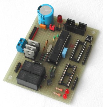
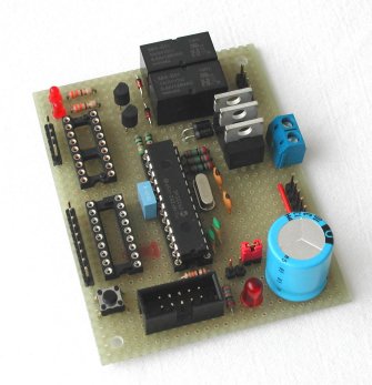
The potmeters can be connected directly to the PHCC Motherboard, the aircores to a stepper/aircore PHCC Daughterboard and the motors to digital outputs. That implies a lot of wiring. I decided to develop a PIC-based PHCC "Manual Trim" daughterboard for the following reasons.
|
In the final design, the control logic for the MANUAL TRIM panel is a mix. The motors are controlled
by the local processor, and one of the two potmeters of each motor is read by the local processor. The second potmeter of each
motor is connected to the PHCC Motherboard so that the trim wheel setting is available for BMS. The aircores are controlled by a
PHCC stepper/aircore daughterboard (with aircore firmware).
I have chosen hex 54 as the PHCC address for the "Manual Trim" daughterboard. Hex 54 is ASCII "T" (for Trim). To address the required functionality the following sub-addresses are implemented in the firmware. |
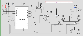
Click the image for a detailed schematic |
| sub-address | data byte | description |
|---|---|---|
| 0 | 0 1 | ROLL trim adjust request
decrease (rotate conter-clockwise) increase (rotate clockwise) |
| 1 | 0 1 | PITCH trim adjust request
decrease (rotate conter-clockwise) increase (rotate clockwise) |
| 2 | 0 ... 255 | Motor (trim) speed |
| 3 | 0 1 2 | Diagnostic LED usage mode
LED off PHCC message acknowledge heartbeat mode |
| 4 | 0 ... 255 | 8 digital outputs |
| 5 | 0 ... 15 | 4 digital outputs |
| 6 | 70 ... 180 | ROLL center position definition |
| 7 | 70 ... 180 | PITCH center position definition |
| 8 | don't care | Rotate ROLL & PITCH trim to center position |
| 9 | 0 ... 255 | Watchdog time-out on trim
wheels centering action. 0 :: time-out disabled 1 ... 255 :: time-out in increments of 100 ms |
| 10 | 0 ... 255 | Motor running time per trim adjust request. 0 :: return to default setting (200 ms) 1 ... 255 :: running time in increments of 10 ms |
 |
 |
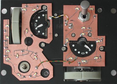
I was glad that I made that choice, because the shape of the boards is not quite a standard rectangle. I made an error in cutting the "island" for one LED of the left side board, but that is solved using a simple wire to connect the LED to +5 Volt.
The method used to make the backlight with thin copper-clad circuit board is described in the description of the
EPU panel and the AIR COND panel.
There are quite a few connections to and from the MANUAL TRIM panel. As with other panels, I try to keep sensitive signals as much as possible away from potentially disturbing signals. This is what I have chosen.
 |
 |
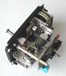
The picture at the left side shows the completed MANUAL TRIM panel. The wiring from the control board
to the controls and motors is done, but this picture is more clear without the wiring.
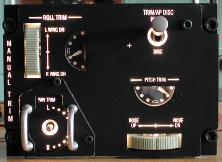
The picture at the right side shows the illumination with the backlight LEDs on at maximum brightness. Note that the illumination
of the dials is not turned on. The dial illumination is wired separately, so that the backlight and instrument illumination
can be controlled separately. However, there is a clearly visible difference between the PITCH TRIM
and the ROLL TRIM dial. I will probably wire the panel backlight and the dial illumination in parallel
in the connector. So, the MANUAL TRIM panel itself has both options available.