| HYD PRESS indicator project
How to interface a real instrument ... |
 |
Introduction
On the Right AUX Console at the top are 2 small round indicators HYD PRESS to indicate the
hydraulic pressure of the two systems in the F-16. It would be nice to have these indicators working, and the AIC project
realizes this with an aircore. See for more information the Vipercore F16 support site,
specifically (AIC > Right console).
For the HYD PRESS indicators this is probably the best solution. The diameter of the (real)
indicator is just one inch, so there is no servo or stepper motor, unless you can find really small ones.
I have scored on eBay two real HYD PRESS indicators, "No.1" and "No.2", and it would be a
shame to destroy them to drive the needle with for example an aircore. So I started to collect information to construct an
electrical controller to interface the HYD PRESS indicator without any modification
to the PHCC hardware.
Operation of the HYD PRESS indicator
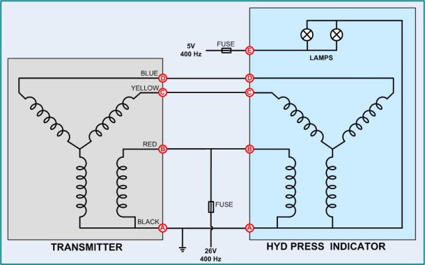
The HYD PRESS indicator contains a so-called "synchro", also known by the old name "selsyn".
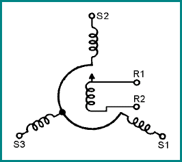
A "synchro" has some resemblance with a 3-phase motor, although this comparison is actually not correct. Anyway, a single phase
coil in the rotor is driven by an AC voltage and 3 coils form the stators. These 3 stator coils are electrically positioned at
120 degrees angle respective to each other. Depending on the phases of the AC voltage on the 3 stator coils the rotor will settle
at a specific position to align with the magnetic fields.

The "synchro" in the indicator (in this case the HYD PRESS indicator) is called the receiver.
So, there must be a transmitter. The transmitter is in fact much like the receiver! The rotor coil of the transmitter is connected
to the same AC voltage as the receiver "synchro".

However, the rotor axis of the transmitter "synchro" is mechanically driven to a position which
represents the unity that must be measured, and indicated on the receiver "synchro". As the rotor of the transmitter "synchro" is
set to a specific position, the AC voltage in the rotor will induce a certain voltage level with a phase shift relative to the
AC voltage in the rotor plus the position of the rotor (with 120 degree phase shifts) in the 3 stator coils. These 3 voltages are
connected to the stator coils of the receiver "synchro" and force the needle of the indicator to settle at a position matching the
position of the rotor axis of the transmitting "synchro".
So far for some theory.
The rotor voltage is an AC voltage with a certain frequency. Common values are 60 Hz (or 50 Hz) and 400 Hz. The 400 Hz systems
are common in airplanes. Transformers (and motors ...) need less iron at higher frequencies, so they weigh less. Because the coils
are designed to operate at the higher frequency, the coil has a lower inductance at lower frequencies.
This means that if a coil is designed for, let's say, 26 Volts at 400 Hz (which is the case for the
HYD PRESS indicator), you can not connect it to 26 Volts at 60 Hz.
Chances are very high that the coil(s) in the HYD PRESS indicator will be
permanently damaged,
if you connect the specified AC voltage level with a lower frequency!
Checking the understanding of operation

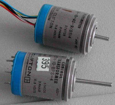
I went to a HAM amateur radio flea market (that is an other hobby of mine) and found a transmitter and a transformer for just 3 euro
each! The nice thing of these synchros is that all the specifications are printed on the housing. On the transmitter the following text
is printed:
400 Hz , ROTOR 1 PHASE 115 VOLTS , STATOR 3 PHASE 11.8 VOLTS.
So, this is a great unit to play with. Running the rotor at 50 Hz, the voltage should be 115 Volts * [50/400] = 14.385 Volts.
I have put 12 V AC 50 Hz on the rotor and connected 2 of the stator coils to my oscilloscope (the third coil is connected to one
of the rotor connections as common ground). I was a bit surprised at what I saw ... The amplitude of the 2 stator coil voltages
indeed varied with the position of the rotor, but the signals were not 120 degrees shifted in phase, but either 180 degrees or 0
degrees! Not sure about this, perhaps I made a measurement error with my scope. Anyway, confirmed is that the amplitude of
the stator signal varies with the rotor (axis) position.
Further reading information
- I found some very interesting information while crawling the internet! Quote:
-
There is a common misconception that a selsyn/synchro is a 3-phase device. For the usual motion control application, this is not true.
Time-wise, the voltages are either in-phase or 180 degrees out of phase with respect to a reference. As the synchro shaft rotates at a
constant rotational velocity, the AMPLITUDES (forgive my shouting) vary sinusoidaly and are 120 degrees apart with respect to the
MECHANICAL (I did it again) position. To generate these voltages, you only need to generate a single phase (electrically) sine (or
pseudo-sine) wave of an appropriate frequency, for example, 400 Hz. You then vary the amplitudes of the other two voltages so that they
vary sinusoidally 120 degrees apart with respect to the desired mechanical position of the shaft.
As regards the quality of the sine, fuhgeddabowdit, I've seen some truly hideous signals driving aircraft synchros just fine.
One other thing. Most synchros will work just fine in an 'S2 grounded' configuration where you ground one of the legs -S2- and only
need to drive the other two.
So, in the end it seems that I only need one sine wave signal! This signal is connected to the rotor as the reference signal.
The same sine wave is also connected to the two stator coils, but can be varied independently in amplitude and sign (positive or
negative with respect to the reference sine wave). To make the axis rotate continuously these two stator coil voltages must vary
sinusoidal with respect to the reference signal. To my understanding, this means that to obtain a steady indication the sine wave
amplitude of the two stator signal must have a specific amplitude.
How to read about the realization of this project
I have split the design in several topics.
- Sine wave oscillator design ideas and final design choice
- Selecting the polarity (sine wave in phase or 180 degrees phase shifted)
- Voltage-controlled gain amplifier
- PHCC Analog Output PWM signal to DC voltage level conversion
- Output stage (power) amplifier
You can read about these topics when you open the "Design ideas" folder in the
"HYD PRESS indicator".
This solution requires 2 analog outputs and 2 digital outputs of PHCC daughterboards per indicator.
It is also possible to design a PIC board using the PHCC DOA communication channel where several analog and digital outputs are
realised; this would be the "PHCC synchro daughterboard".
to be continued ...


