| Horizontal Situation Indicator (HSI) AQU-13/A
Another eye-catching complex instrument |
 |
Introduction

One of most complex instruments in the pit is the Horizontal Situation Indicator, HSI.
That becomes obvious when you look at the rear side of the instrument ...
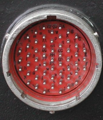
One large many-pins connector socket, 55 pins if I counted correctly!
The following indicators in the HSI can be controlled, going "clockwise" starting in the top left corner.
- Miles indicator
- (ILS/NAV , NAV) Displays the nautical miles to the destination.
- (ILS/TCN , TCN) Displays slant range nautical miles to TACAN station.
- Range shutter
- (ILS/TCN , TCN) Red and white striped bar covers MILES indicator when
TACAN beacon is out of reception range, TACAN system is off, or TACAN
system DME circuit fails.
- (ILS/NAV , NAV) Red and white striped bar covers MILES indicator when
INS is off or operating in attitude mode.
- Course indicator
This is a 3-digit counter which displays the selected course set by the CRS control.
- OFF flag
When visible, indicates loss of external electrical power input or internal power supply failure. Compass card, course arrow,
heading marker, and relative bearing pointer become inoperative. MILES indicator, COURSE
indicator, CRS control, HDG control, deviation bar, and range shutter remain operative.
- CRS control - Knob used to set COURSE indicator and position course arrow to desired course indication.
- HDG control - Used to position heading marker to desired heading indication.
The following indicators are in the "center" part of the instrument.

- Compass card - The large 360 degrees round scale which indicates the aircraft magnetic heading with respect to the fixed
lubber lines.
- Course arrow - Indicates selected course set by CRS control with respect to compass card.
- Relative bearing pointer
- (ILS/NAV , NAV) Indicates relative bearing to destination with respect to compass card.
- (ILS/TCN , TCN) Indicates relative bearing to TACAN station with respect to
compass card.
- "TO - FROM" indicator
- (TCN) Displays white in triangle nearest nose of miniature aircraft symbol when selected course is within
+/-90 degrees of indicated relative bearing or white in triangle nearest tail of miniature aircraft symbol when selected course is
greater than +/-90 degrees of indicated relative bearing.
-
(ILS/TCN , ILS/NAV , NAV) Displays open triangles (white mask out of view).
- Course/Localizer deviation bar
- (TCN , NAV) Indicates course deviation from selected course with respect to relative bearing indication.
Amount and direction of deviation is with respect to deviation scale. Each division (dot) on the deviation scale represents 5
degrees deviation from the selected course with respect to relative bearing indication. Maximum determinable deviation indication
is either 10 degrees left or 10 degrees right.
- (ILS/TCN , ILS/NAV) Indicates ILS localizer deviation from ideal flightpath approach with respect to
deviation scale. Each division (dot) represents 1.25 degrees deviation from the ideal ILS flightpath approach. Maximum
determinable deviation indication is either 2.5 degrees left or 2.5 degrees right.
- Deviation warning flag
- (TCN) Displays red rectangle when TACAN system is off or TACAN
system is unable to track beacon bearing signal (beacon out of range or TACAN system failure).
- (ILS/TCN , ILS/NAV) Displays red rectangle when landing approach transmitter is out of reception range,
ILS is off, or ILS fails.
- (NAV) Displays red rectangle when INS is off or operating in attitude mode.
- Heading marker - Indicates heading selected by HDG control with respect to compass card.
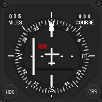
While powerless (no connections made to the HSI), the HDG knob does move the heading bug (the small white
rectangle with the black stripe in the middle), in the picture at 298 degrees. The CRS knob has no effect
when you rotate it.
Note that the COURSE drum counter and the CDI arrow (Course Deviation Indicator) both show "143"! It gives
me hope that at least something of this HSI is still in working order ...
HSI indicators
 |
There are a lot of indicators on the front of the HSI.
- Range indicator
- Warning flag - range indicator
- Heading reference marker
- Upper lubber line
- Course selector window
- Bearing pointer
- OFF warning flag - HSI power
- TO-FROM indicator
- Miniature aircraft symbol
- CRS set knob
- Course arrow - tail
- Bearing pointer - tail
- Lower lubber line
- HDG set knob
- Course deviation indicator
- Course deviation scale
- Warning flag - course deviation
- Course arrow
- Compass card
(Original image drawn by "lightning") |
Connection data
The big connector at the rear side of the HSI does not have pin numbers, but letters.
All presented information is very preliminary - do not assume any correctness !
The pin letters in the following table are taken from an Astronautics Corporation of America information sheet.
They seem to match the connector, but the descriptions are rather vague.
| Connection information taken from an Astronautics data sheet |
|---|
| pin letter | function |
|---|
| A | course resolver input ORZ |
| B | test point or spare |
| C | heading flag return (-) |
| D | test point or spare |
| E | test point or spare |
| F | heading stator input (X) |
| G | heading stator input (Y) |
| H | heading stator input (Z) |
| J | case ground |
| K | test point or spare |
| L | test point or spare |
| M | heading datum output (H) |
| N | heading datum output (C) |
| P | bearing pointer no.2 stator input (X) |
| R | bearing pointer no.2 stator input (Y) |
| S | bearing pointer no.2 stator input (Z) |
| T | test point or spare |
| U | signal ground |
| V | test point or spare |
| W | course datum output (H) |
| X | course datum output (C) |
| Y | 5 Volts 400 Hz return |
| Z | test point or spare |
| a | course resolver RW1 (A) |
| b | course resolver RW2 (B) |
| c | course resolver RW 1/2 (C) |
| d | course resolver output SW1 (D) |
| |
| pin letter | function |
|---|
| e | course resolver output SW1 (E) |
| f | course resolver output SW2 (F) |
| g | course resolver output SW2 (G) |
| h | distance display shutter (-) |
| i | test point or spare |
| j | digital data input - high |
| k | test point or spare |
| m | decoded course deviation signal (+) |
| n | decoded course deviation signal (-) |
| p | decoded bearing no.1 signal (+) sine |
| q | decoded bearing no.1 signal (-) sine |
| r | digital data input - low |
| s | digital data shield ground |
| t | course deviation pointer (-) |
| u | course deviation pointer (+) |
| v | TO - FROM arrow (-) |
| w | TO - FROM arrow (+) |
| x | decoded NAV flag signal (+) |
| y | decoded NAV flag signal (-) |
| z | 5 Volts 400 Hz integral lighting |
| AA | 115 Volts 400 Hz return |
| BB | 115 Volts 400 Hz primary power |
| CC | decoded bearing no.1 signal (+) cosine |
| DD | decoded bearing no.1 signal (-) cosine |
| EE | navigation flag (+) |
| FF | navigation flag (-) |
| GG | heading flag (+) |
| HH | test point or spare |
|
Notes:
- "ORZ" : Omni Range Zero (VOR system).
- The HSI needs 26V AC 400 Hz for the excitation of the MILES indicator and the TACAN system D/A converter.
- The HSI needs 115V AC 400 Hz for the operation of the OFF flag, but is also required for several
synchros and other electronic circuits.
|
The letters in the following table are taken from F-16 schematic diagrams, but you can see that it
does not match the real connector ...
It seems that the capital letters followed with an asterisk denote that they are actually a lowercase letter.
| Connection information taken from schematic diagrams |
|---|
| pin letter | function |
|---|
| A | ? ORZ |
| B | ? Course Drive Enable |
| C | ? Course Drive Enable |
| D | ? Rotor phase bearing ("HOT") |
| E | ? Rotor phase selected course output ("HOT") |
| F | magnetic heading (input) synchro S3 |
| G | magnetic heading (input) synchro S2 |
| H | magnetic heading (input) synchro S1 |
| J | GND selected course synchro R |
| K | 26V AC 400 Hz HOT |
| L | ? |
| M | ? Course datum output "GND" |
| N | ? Course datum output "HOT" |
| P | relative bearing synchro S1 |
| R | relative bearing synchro S2 |
| S | relative bearing synchro S3 |
| T | selected course (output) synchro S1 |
| U | selected course (output) synchro S2 |
| V | selected course (output) synchro S3 |
|
| pin letter | function |
|---|
| W | magnetic heading output "HOT" |
| X | magnetic heading output "GND" |
| Y | ? |
| Z | +5V "gnd" internal lighting return |
| a | ? course datum (output) synchro S1 |
| b | ? course datum (output) synchro S2 |
| c | ? course datum (output) synchro S3 |
| d | ? selected course (input) synchro S1 |
| e | ? selected course (input) synchro S2 |
| f | ? selected course (input) synchro S3 |
| g | ? selected course (input) synchro S2 |
| h | range shutter (-) |
| i | range shutter (+) |
| j | GND MILES ind 100-10-1 synchro S3 |
| k | 26V AC 400 Hz HOT MILES ind |
| l | MILES ind range 1 synchro S1 |
| n | MILES ind range 1 synchro S2 |
| p | MILES ind range 10 synchro S1 |
| q | MILES ind range 10 synchro S2 |
|
| pin letter | function |
|---|
| r | MILES ind range 100 synchro S1 |
| s | MILES ind range 100 synchro S2 |
| t | course/localizer deviation bar (-) |
| u | course/localizer deviation bar (+) |
| v | TO - FROM indicator (-) |
| w | TO - FROM indicator (+) |
| x | ? |
| y | +5V "hot" internal lighting |
| z | ? |
| AA | 115V AC 400 Hz GND OFF flag |
| BB | 115V AC 400 Hz HOT OFF flag |
| CC | ? |
| DD | ? Rotor phase magnetic heading ("HOT") |
| EE | deviation warning flag (+) |
| FF | deviation warning flag (-) |
| GG | ? 28V DC ADF select |
| HH | ? 28V DC GND |
| | |
| | |
|
The letters in blue in both tables indicate that they match with each other, but that is no guarantee. Careful checking is required!
If a "pin letter square box" is colored yellow, it indicates that the connection is checked and correct. Lots of question marks though ...
Power supply : 26 Volt 400 Hz
- Introduction
Just like the ADI, the HSI requires a 400 Hz power supply voltage. In case of the ADI the voltage is 115V AC, but the HSI also
needs 26V AC. The power supply for 115V AC 400 Hz can be the same design as used for ADI. However, the approach used for the ADI
with an output transformer is not usable for the 26V AC 400 Hz power supply. If the class D amplifier could be substituted with
something else capable of delivering 2 Amps, it could be a solution. The current requirement comes from the schematic diagram of
the HSI "environment". In the drawing the HSI is connected to a transformer. Input voltage is 115V, and the output voltage is 26V.
Text next to the transformer says "50VA". I doubt that amount of energy is needed.
My initial design used an OpAmp that drives a push-pull output stage using a TIP29 (NPN) and TIP30 (PNP) transistor. Several
components and a heat sink are needed. Searching for "high current" and "high voltage" OpAmps, I found the OPA548 OpAmp. That
IC includes everything needed, and more, than the transistor push-pull output design. The OPA548 can supply 3 Amps continuous, has
a wide power supply range up to +/-30 Volt, and additionally the OPA548 can be current limited and has thermal shutdown protection.
The OPA548 still needs a heat sink, but the design is less complex and a lot more "fool proof" against mis-use.
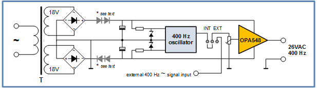
Thus, the design of the 26V AC 400 Hz power supply consists of the already described 400 Hz oscillator (see ADI), the OPA548,
and a DC power supply. The DC power supply can be simple.
Dual DC power supply and the 26V AC 400 Hz power supply
- Dual DC power supply
The 26V AC 400 Hz power supply is as you can see from the block diagram, actually just an Operational Amplifier, but then a
beefy one! As any OpAmp, it needs a DC power supply, and in this case a symmetrical DC voltage. The dual power supply consists of
a mains transformer with two 18V or 20V secondary windings. The windings connect to bridge rectifiers and the output is smoothed
with big polarized capacitors. The only specs to observe are that the windings must be capable of delivering some 2 Amps (transformer
is rated 50VA), the bridge rectifiers must be able to handle the current, and the polarized capacitors must be rated at least for an
operating voltage of 50 Volt. Possibly the 18V output of the transformer is a little low, and should be 20V, but an 2x18V 50VA
transformer was on my shelf.
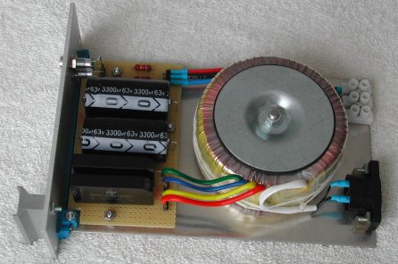
Dual +/- DC power supply
After the dual DC power supply is built, the output voltage must be checked. Depending on several factors, not in the least the
secondary voltage of the transformer windings, the voltage must be lower than 30 Volt DC to protect the OPA548
against too high supply voltages. +/-30V is the absolute maximum rated supply voltage for the OPA548. If the output voltages are
too high simply put in the (+) and the (-) output terminal one or more diodes in series that can handle the current. Normally we
do not want the voltage drop caused by a diode, but in this case we want it!
Without any load on the output of the dual DC power supply, I measured +25.55V DC and -25.53V DC with 18V secondary windings.
So you could probably use a transformer with 20V secondary windings, but if the windings have a higher voltage rating you will
have to add diodes at the output of the bridge rectifiers to get the needed voltage drop.
- 26V AC 400 Hz power suppy
The 26V AC 400 Hz power supply consists of two "building blocks". The first block is the 400 Hz sine wave oscillator. This is
built using an LM358 OpAmp. The +26V and -26V DC power supply is too much to handle by the LM358, so these supply voltages
are regulated to +9V and -9V using two zener diodes with a suitable shunt resistor. The output of the oscillator is a small
sine wave, amplitude approximately 0.5V. As the LM358 has two OpAmps, the second OpAmp amplifies the signal by a factor 10.
This means that the amplitude of the sine wave presented to the OPA548 is already some 5V, thus the OPA needs to amplify the
input signal just by a factor 5 to obain the desired "26V AC 400 Hz".
The second block is of course the OPA548 power OpAmp. This IC contains everything, so the needed external components are
limited to setting the amplification factor of the OpAmp, setting the current limiting value for protection against overload,
and the proposed capacitor decoupling and output protection needed in case an inductive load produces sufficient energy to
"lift" the output voltage above the maximum allowed by the connected power supply. In the end, the design still needs quite
some components, but it is easier than the discrete push-pull transistor design. Did I say that it is an easy power supply
solution? Nothing comes for free ... the OPA548 is not cheap (I paid 20 Euros for it)!

The 400 Hz oscillator and AC power amplifier
According to the specification sheet of the OPA548, there is a non-symmetrical voltage drop at the output. That is, the output
cannot swing rail-to-rail. The voltage drop is slightly higher for the positive voltage level compared to the voltage drop of
the negative voltage level. Given a power supply voltage of some +26V/-26V DC, the amplitude of the output can be expected
symmetrical almost 23V. That is a bit lower than the 26V AC for the HSI, but I don't expect the slightly lower AC voltage will
cause any problems. After all, the "26V AC" is only needed for the synchros. They will work fine at 23V AC (400 Hz).
Big mistake !!
The dual DC power supply is working fine, and the OpAmp also. But there is a big thinking mistake in the reasoning
of the above described "26V AC 400 Hz" power supply! The peak amplitude of the sine wave output will be approximately 23V,
but the effective voltage level will be 0.707 lower (0.5 * sqrt(2)) and that is more like 17V AC 400 Hz. And that is exactly
what I measured! So, given the absolute maximum rating DC supply voltage of the OpAmp is 60V (that is +30V / -30V symmetrical),
it is not possible to build a 26V AC 400 Hz power supply with this OpAmp. However, if 1:2 ratio 400 Hz 50VA transformer
can be found, you can drive the primary of the transformer with the output of the OpAmp, and get 26V AC from the secondary ...
time to check out eBay ...

Lucky me, I found a transformer in the EU (no additional Customs tax) that could be exactly what I need. The information printed
on the housing is clear, and given all connection options at the secondary side, it would be just fine. However, what is not (yet)
clear, is the power rating. But at a cost of 11.50 Euro (plus 11 Euro shipping cost), it is worth taking a gamble. Searching the
internet reveals that the application is "audio". That seems to be a little strange to me, because of all the selectable output
voltages. I would expect a transformer ratio or impedance information on it for audio application. I will have to wait until I get
the transformer in my hands ...
Got it! And it is probably a power transformer, because the transformer came in its original shipping box, with a label attached to
the box, saying
               5950000070703
     FSCM  15634  MFR/PN 02424
     TRANSFORMER,  POWER,  S
     1 EA
     DLA900-83-P-F317
     A        7/83
|
So it is probably a power transformer after all! And given its size (42x42x52 mm), it is probably capable of handling some
energy.
Driving the HSI
The HSI is a complex instrument and has a lot of functionality. Most of the features can be operated separately, so that is my
approach to get the HSI bit by bit fully functional. That's what I hope to achieve ... we'll see.
I have one HSI instrument
but it has a dent through the metal housing, I hope nothing is damaged and that everything inside is still OK.
Another problem is of course that the two tables with pinout description do not match 100%. I will start with the functions
that probably do not need external power, but are "self-operated", such as the range shutter, course/localizer deviation bar
and deviation warning flag.
- Internal lighting
Initially, I could not get the internal bulbs light up. I feared that they were burnt out. But thanks to information from
"Nigel" and "lightning" it became clear that the Astronautics info is not applicable to this HSI. For the
internal lighting the +5V (400 Hz, but this is not thát significant) must be connected to "lowercase y", and the +5V return
must be connected to "uppercase Z". Sort of other way around compared with the Astronautics data sheet.
-- Internal lighting is working!
- Range shutter
The range shutter is a simple flag. It is visible when no power is applied. When power is applied the flag moves out of the
view field, no longer covering the 3-digit counter of the MILES indicator. The shutter flag needs a
simple on/off digital signal. AQU-6/A info: the shutter mechanism is excited with 28V DC. My tests show that the range shutter
is connected to pins (i) and (h). So that is a mismatch with the Astronautics datasheet, where (i) is denoted "test points and/or
spares"! When connected to 15VDC the range shutter does work, but very "sluggish". Operation is fine at 24 VDC, and the measured
current is 21 mA. -- Working!
- TO - FROM indicator
The TO - FROM indicator are two small triangles that normally are not visible. When a voltage is applied
it depends on the polarity whether the "TO" or the "FROM" flag is shown. AQU-6/A info: coil resistance 200 Ohm +/-15 Ohm.
Maximum current for full displacement is 225 microAmps. Astronautics info: coil resistance 200 Ohm, 200 - 0 - 200 microAmps.
The TO - FROM indicator is connected to pins (v) and (w) which matches both tables. A test with 20VDC and
a series-resistor of 100 kOhm results in a measured current of 210 microAmps. When (w) is connected to positive voltage and (v)
to GND, the TO flag appears. When (w) is connected to GND and (v) to positive voltage, the
FROM flag appears. -- Working!
- Deviation warning flag
The red rectangle a little out of the center of the instrument is visible when no power is applied. When power is applied it
disappears. The warning flag needs a simple on/off digital signal. AQU-6/A info: coil resistance is 1000 Ohm +/-3%. A current
below 180 microAmps keeps the flag visible. The flag is completely disappeared with a current of 245 microAmps. Astronautics
info: "NAV flag" 1000 Ohms, 245 microAmps. Initially, the warning flag was not working. You would not expect it, but 115V AC
on pins AA and BB is required to make this flag disappear. I did not test with a series resistor (to limit current), because
"lighting" wrote that you can connect 28V DC directly. Being careful, I started with 5V DC ... the red rectangle
disappeared! It even disappears when the DC supply voltage is turned down to 1V. Some more experiments *with* a series resistor
will be done to find an always correctly operating deviation warning flag with an as low current as possible.
-- But the deviation warning flag works!
- Course/localizer deviation bar indicator (CDI)
The course/localizer deviation bar indicator shows the course deviation from selected course with respect to relative bearing
indication. The deviation bar needs an analog signal that can swing between a negative voltage and a positive voltage. AQU-6/A
info: coil resistance is 1000 Ohm +/-3%. The deflection requires 75 microAmps +/-6 microAmps per dot. Astronautics info: 1000
Ohms, 150 - 0 - 150 microAmps.
Correct connections not yet found or the CDI needs a power supply (or
the CDI is defective ...)
- Miles indicator
The MILES indicator is a 3-digit drumcounter. The diagram shows the connections of the MILES synchros. The
number of synchros that has to be controlled for an HSI increases rapidly, because just for the MILES
indicator three synchros are used, one for each digit. Luckily, these synchros only use 2 of the 3 stator coils.
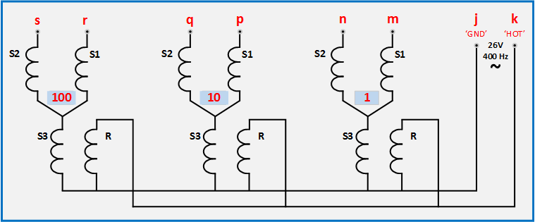
These are the values I measured using a standard Ohm meter. Note that the numbers are the DC resistance values, and are not
correct when the coils are driven by a 400 Hz AC sine wave. For example, the resistance between connection "s" and "r" (two
stator coils in series) is 37 Ohms at DC, but 67 Ohms at 120 Hz, and 214 Hz at 1 kHz (those frequencies are available on my LCR
meter). Further, the inductance between these two connections 62 mH at 120 Hz, and 58 mH at 1 kHz.
| connection points | s - r | s - j | r - j | s - k | r - k |
|---|
| DC "resistance" [Ohm] | 37 | 36 | 36 | 64 | 64 |
| |
| | q - p | q - j | p - j | q - k | p - k |
|---|
| | 12 | 11 | 11 | 39 | 39 |
| |
| n - m | n - j | m - j | n - k | m - k |
|---|
| | 37 | 37 | 37 | 65 | 65 |
Although the "tens-digit" synchro coils show different lower values, I have the impression that the drawn schematic is correct.
Time for a test setup. I connected the "26V AC" power supply with the transformer, and using the correct taps on the secondary,
I get 26V AC! I connected that to the HSI and to the rotor of an external synchro (once bought on a radio amateur flea market).
I connected two stators of the external synchro to the HSI pins "n" and "m" (unit drum counter reel), but when I rotate the axis
of the external synchro nothing happens. Next attempt. Connecting the third stator of the external synchro to the rotor of that
synchro. Rotating the axis of the external synchro now controls the unit drum counter reel of the MILES indicator.
However, I want to control the drum counter reel with electronics, not real external synchros. As there are only two stator coils
available from the HSI (for one drum counter reel), I have to generate the correct signals. The solution used for the ADI (3 stator
signals each at 120 degree phase shift from each other) will not work.
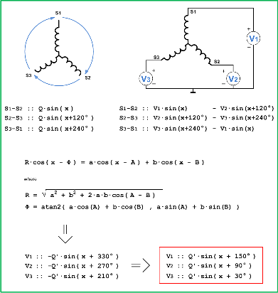
I think that for one stator connection of the HSI you have to "look" at the electrical substitution. And that is a connected digit
stator coil *in series* with the stator coil connected to the rotor. Using a bit of trigonometry I *think* you can drive the number
reel with just two "SDI outputs", but the phase shift is not 120 degrees, but 60 degrees (that is the result of the trig math).
Click on the image to see a larger, better readable image of the math.
So, assuming that the rotor sine wave has a "phase shift" of 0 degrees, the coil S3 also has a signal with 0 degree phase shift.
According to the trigonometry and assuming a 0 degree phase shift on coil S3, the proper phase shift to be applied to S1 should
be 60 degrees (90 - 30). And the proper phase shift to be applied for S2 should be 120 degrees.
to be continued ...
- OFF flag
According to the diagram of the AQU-4 and AQU-6, and the F-16 HSI schematics drawing, 115V AC 400 Hz must be connected to pins
AA ("GND") and BB ("HOT"). I need that 115V power to continue any experiment, because that voltage supplies the rotor energy
for several synchros inside the HSI. No guts, no glory ...
I connected the 115V to AA-BB. The OFF flag moves out of the visible field!
- Magnetic heading
The magnetic heading is the most prominent part of the HSI. It is the big compass rose. Now that the 115V power supply is OK,
I can use an external synchro to do some "educated" tests on a few connection pins. (I have two synchros for test purposes,
one with a rotor for 26V supply voltage, and one with a rotor for 115V supply voltage.) Connecting the external synchro
stator connections to the HSI pins F, G, and H makes the compass rose rotate, and I can position
the compass rose to any position!
- Relative bearing pointer and Heading marker
At the outer circle of the compass rose are the so-called "relative bearing pointer", which is a white triangle, and the
"heading marker", which is a white rectangle with a small divider bar.
- Relative bearing pointer
The relative bearing pointer is controlled with a synchro. Again, using the diagrams of the AQU-4 and AQU-6, and the F-16 HSI
schematics drawing, my conclusion is that the rotor of that synchro is powered from the 115V AC 400 Hz (via the internal
transformer) and the stator connections are on pins P, R, and S. -- Checked, I can position
the relative bearing pointer!
- Heading marker
The heading marker, also called "captain's bars", can be positioned by rotating the HDG knob, and
it moves even when no power is applied to the HSI. The knob is mechanically connected to the heading marker and the axis of a
synchro. The three stator signals of this synchro are connected to pins F - G - H. This is the magnetic heading input (compass
rose), and makes the heading marker "follow" the compass rose. The rotor connections of the synchro are available on pins W - X.
The output amplitude must be converted to an angle (0 ... 360 degrees) and must be fed back to BMS. The feedback of the angle
information can be realized with two different approaches, both starting with the conversion of the angle to digital data(bits).
The first method uses CMOS switches to pass 9 or 10 data bits to the pit interface hardware via a key matrix. If the design has
a USB connection, the data can be transmitted using the USB connection. The second method uses the (internal) digital data to
drive a DAC (Digital to Analog Converter). The output of the DAC (an analog voltage) can be fed back to BMS via an analog input
which can be implemented as a "virtual joystick". The second method is preferred.
- Course arrow and numeric window
The course indication consists of an arrow and a mechanically linked 3-digit numeric display window.
to be continued ...