| Backlighting for panels
LED backlighting ... integrated in the panel ! |
 |
Viperpit panels
All panels are in fact made of two layers of plexiglass.
The top layer is painted somewhat white at the rear side, and the front side is what you see: painted black with laser-engraved
text legends. The text legends appear as white text, because of the white paint on the rear side.
The other layer is just transparent and glued onto the rear side of the other layer. The thickness of the transparent layer
plexiglass is some 2 mm, or even more for some panels.
New solution with SMT LEDs
Modern SMT LEDs are a bit less than 2 mm thick, so why not cut small "holes" in the transparent plexiglass?
The same "trick" is used for the required series resistors and the wiring.
There is just one drawback : the connection wires "come out" of the panel, so are vulnerable to break (near the panel of
course)!
A solution for this problem is a bit of hot glue and a small 2-pin connector.
Implementation details
First, you determine by experimentation where you needs LEDs.
To obtain a reasonably uniform lighting of all text legends you will quickly need some 10 LEDs for a small panel!
It depends on the number of text legends and their location on the panel.
- Solder an (SMT) series resistor directly to the anode of each LED. The LED I used is from Ledman, type LS-AOHB-CSN3-02.
Solder a piece of enamel-lacquered (insulated) 0.3 mm diameter wire to the resistor and the cathode of the SMT LED. The resistor
value I used is 165 Ohm, which will cause some 13 mA current with a 5 Volt power supply and a lot of bright light!

SMT resistor with SMT LED soldered to wires (wire is 0.3 mm diameter!)
- After you determined the number of LEDs needed, and their location on the panel, you drill holes in the transparent
plexiglass. Take care that you do not drill through the plexiglass! After that you use a Dremel cutter (3 mm diameter) to make
the holes larger, not deeper. The size and the depth must be such that the SMT LED with the series resistor can be put in it with
its wires, and it does not protrude from the rear side of the transparent plexiglass.
- Next is the cutting of the plexiglass for the wiring.
I use 0.3 mm wire (the type also used in coils and transformers). You
can buy this wire on rolls of 50 meters for just a few Euros. I use this wire also for all my protoype circuit boards! With
the Dremel cutter you can cut the "trenches" in the rear side of the panel for the routing the wiring.
- Put the LED with resistor with the wires in the panel. Guide the wires through the cut slits in the panel.
Solder the ends of the wires to each other, and then place the soldered joint in the slits. Distribute the soldering joints.
After you have done the top "group" of some LEDs check that this group lays flat in the drilled "pockets". If the group does not
protrude, check with a power supply that all LEDs light up, then fill the "pockets" and "trenches" with hobby glue.
- Repeat the described procedure for the bottom group of LEDs.
- Finally, cut a small hole for the 2 pins of the "terminal". The 2-pin terminal is a 90° angle circuit board header. Solder
the wire ends and use glue to fix the terminal in the panel.
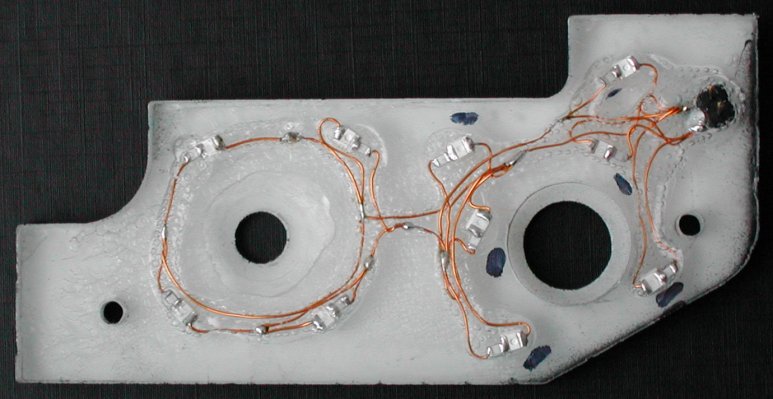
ten (!) SMD LEDs installed in FQS panel back side with 2-pin header
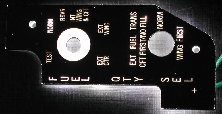
FQS panel backlit with 10 LEDs