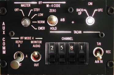
| AUX COMMUNICATIONS panel
Thumb wheels and a rotary switch with a "feature" |
 |
Introduction
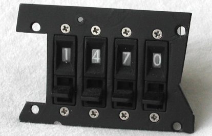
On the AUX COMM panel is the eye-catching 4-digit "thumb wheel" selector, a 3-position "flat-top"
switch (lock type F), 2 normal lever 2-position switches, one "round-top" 3-position switch (lock type E), and two rotary
switches. You can sometimes find the 4-digit thumb wheel selector on eBay, or build a solution using displays and 4 small
momentary thumbler switches.
Both rotary switches have a step angle of 36°, which is not that common. Knitter, Grayhill and C&K have them. The
CNI rotary switch has only 2 positions, the IFF MASTER rotary switch has 5
positions. However, although not visible from the front panel, according to the F-16 manual, the EMER
position is locked-out. You have to pull the knob to select that position.
Thumb wheel switches

On the Vipercore F16 support site (AIC > Left console) you can see (and
buy) a circuit board that holds two SLG2016 displays and 4 momentary up / momentary down switches for the TACAN thumb wheel
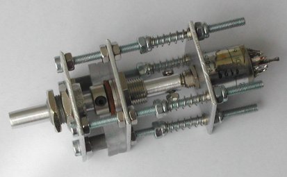
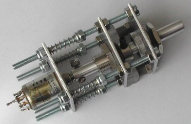
CHANNEL selectors. The original thumb wheel switches used in the AUX COMM panel
are so-called "digitrans". If you want to get these, I would suggest to search on eBay. The product is called "Digilever 24000
Series", but "digitran" or "aircraft flight data panel" are equally good search terms. The picture shown is in fact an "aircraft
flight data panel" found on eBay for $75. The seller noticed the interest in these boxes and raised the start bid to $125 !
However, these thumb wheels all have the numbers 0 thru 9 (10 positions). In the AUX COMM panel only the
mid two thumb wheels have the range 0 thru 9. The leftmost thumb wheel should only have the numbers 0 and 1. The rightmost
thumb wheel should only have the letters X and Y. As the connection
of the thumb wheels is binary coded, you can use the least significant "bit" for the leftmost and rightmost thumb wheel to decode
its position. On Viperpits you can find a description how to modify the thumb wheel switch so that it only has 2 positions. This
involves cutting notches inside the switch. Personally, I do not like that solution ... if you make an error you probably have
a thumb wheel switch that you no longer can use! IMHO, you can better (carefully) use an Exacto knife to scrape the numbers
of the thumb wheel, or use a black felt pen to cover the original numbers and then use white transfer letters that you "rub" onto
the thumb wheel. Of course, you need to have the correct letter height, and repeat "0/1" and "X/Y" five times. Tip: make on the
side of the thumb wheel a marker line to indicate the center of the letter, so that you have to correct position to put the white
transfer letter on the thumb wheel.
If you can get such an "aircraft flight data panel", you can re-use a part of the front panel for the AUX COMM
panel. That way, you do not need to make a metal panel to mount the 4 thumb wheel switches.
The "aircraft flight data panel" box also has a panel on which the thumb wheel switches are mounted, so just use a saw to cut the
piece of metal that you need! Keep in mind to cut the metal plate sufficiently large, because you need to drill holes to mount
this metal plate with countersunk M3 screws onto the backplate of the AUX COMM panel.
Spray paint the metal plate black.
Check that the activation levers at the bottom can move freely sufficiently downwards to change the selected position ... there
is little room for play when the AUX COMM front panel is mounted onto the backplate!
IFF MASTER rotary switch
The IFF MASTER rotary switch has 5 positions with a step angle of 36°. However, according to the F-16 manual,
the EMER position can only be selected after the knob is pulled. See the KY58
page for a description how you can realize that functionality with a few simple aluminium plates, M3 screws and springs from a
ballpoint pen.
Panel backlighting
The backlighting for this panel is a little tricky to realize, because some texts are very close to an edge. For example, the
horizontal bar and the word IFF, and less obvious the word CHANNEL above the
thumb wheel switches. Keep in mind that you have to keep some material around the opening for those thumb wheel switches, so
that from the frontal view the panel "closes" around the thumb wheel switches. This means that there cannot be a PCB to mount
the backlight SMD LEDs. To make the realization a bit easier, I have "cut" the backlighting PCB in two halves. See the
AIR COND panel for a detailed description how the backlighting is made. Here is the paper layout
and the backlighting PCB result.
Result
Most of the work for this panel is of course the rotary switch with the protected position and the recurring job for every panel,
the backlighting PCB with the SMD LEDs. But once the rear side of the panel is cut to make room for the backlighting, and you see
the illumination the first time, you know it was worth all the effort!

|
|
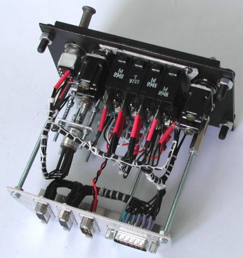
AUX COMM panel with all components |
AUX COMM panel with backlighting on at maximum brightness |
And the panel is not really finished until the wiring is done to a connector plate with sub-D connectors. There are quite a few
switches on this panel (5 for the rotary switch MASTER and 10 (!) for the four thumb wheel switches).
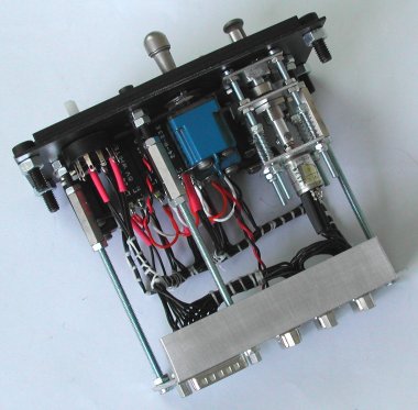
However, due to its position and size, this panel also acts as a switch matrix connection distribution panel. The switch matrix
connection for the left side console is on the ENGINE & JET START panel, but the
AUX COMM panel is the distribution point for the "lower" part of the left side console.
|
|
AUX COMM panel with all components |
AUX COMM panel with backlighting on at maximum brightness |