A very prominent indicator
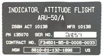
| Attitude and Direction Indicator (ADI) ARU-50/A A very prominent indicator |
|
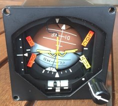
The ADI has one 31-pin socket on the rear side. The instrument requires two power supply voltages, +28 Volt DC and 115 Volt AC, 400 Hz.
The control of the sphere is realized by one synchro for the roll movement and one synchro for the pitch movement. The setting knob
to align the sphere with the horizon is also a synchro that supplies its data to the pitch synchro. Note that if the pitch synchro
has not been set to an appropriate position (and enabled), the setting knob will not function.
The horizontal and vertical deviation bar needle pointers are analog indicators. They are in the "mid" position when their inputs are not driven. A negative voltage is needed to drive the needle pointer down and to the left respectively. A positive voltage is needed to drive the needle pointer up and to the right respectively.
The four flags are controlled by a digital signal. The flags are all visible when no voltage is applied to their control pins. Only the GS, LOC, and AUX can be controlled. The OFF will only disappear when certain conditions are met. These conditions are the presence of both power supply voltages (24V DC and 115V AC), and valid synchro signal voltages (if enabled). Finally, the instrument has light sources to illuminate the indicators in the instrument.
|
|
Some remarks
The previously developed 115V AC 400 Hz power supply based on two switching MOSFETs that drive the secondary coils of a transformer
and producing 115 V on the primary coil was not the ideal design for "reproduction". Further, it needed a dedicated DC power supply,
because the DC output voltage of that power supply was the control to set the transformer output voltage to 115V. However, due to
the design, changing the DC supply voltage also influenced the 400 Hz, so there were two adjustment potentiometers.
Revisiting the earlier ideas of building a nice 400 Hz 115V Volt power supply, I had another look at the design using a standard
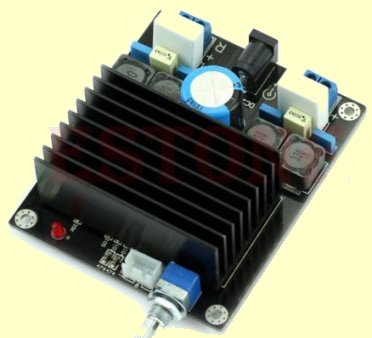
audio amplifier. But I knew that I needed some 30W continuously, so it would have to be a "beefy" audio amplifier. Too lazy
to design an amplifier, and given the fact that there are already so many audio amplifier designs, I checked eBay. To my surprise I
saw audio amplifiers with miniscule heat sinks specifying two 100W channel outputs! The trick here is that conventional high
quality audio amplifiers have so-called class A output stages. That makes the operation of the transistors in the amplifier output
stages very linear, but also dissipating a lot of energy (heat). Hence, class A amplifiers have large heat sinks. For completeness,
class B amplifiers try to limit the dissipation but at the cost of some non-linerarity (distortion). Class C amplifiers are unsuited
for audio amplifiers. However, on eBay there are cheap class D amplifiers. These amplifiers are based on a totally different principle.
They use PWM (Pulse Width Modulation) and switch output MOSFETs (not transistors) at a very high frequency on and off. So that is
very a-linear ... yes, the switching is, but the envelope is accurately following the (audio) input signal! As these MOSFETs are
either in OFF state or in ON state (at least the transition between the states is as short as possible) there is virtually no
energy loss. So, for less than 15 Euro you can get a 2-channel 100W class D amplifier of minimal sizes. I selected one that also
operates on a single 24V DC supply voltage, making the overall power supply requirements very simple, just one 24V DC PSU.
Note that these class D amplifiers have two output terminals for each channel. You must use these two terminals and only
connect the loudspeaker (or something else ...) to these two terminals. Do not use one terminal and "GND" as the other
terminal! Do not use one terminal of one channel and another terminal of the other channel! Both terminals carry a high DC
voltage with respect to GND, but with respect to each other the DC voltage difference is zero, so only the AC component (what we
need) remains between these two terminals.
So, what more do we need?
First, we need a 400 Hz sine wave oscillator. That can be easily realized using one OpAmp. The inputs are biased with half the DC
power supply voltage, so that the oscillator (OpAmp) can operate with a single supply voltage. The frequency determining
components are the two 39k resistors and the two 10 nF capacitors. The 100 nF and other 10 nF capacitor are decoupling capacitors.
The two 10 nF capacitors are a bit high in value. It is better to start with 6n8 or 5n6 capacitors, and measure the frequency. If
the frequency is too high you must lower the capacitor value (replace with a smaller capacitance) or lower the 39k resistors
(adding a higher value in parallel). If the frequency is too high you can increase the capacitance by adding a small
capacitance in parallel.
The signal output of the oscillator is connected to the input of the class D amplifier with a small trim potentiometer ("volume
control").
The output of the class D amplifier is not connected to a loudspeaker (...) but to the 18V secondary coil of a transformer. The 115V primary coil of the transformer gives the desired 115 Volt AC 400 Hz, but the shape of the sine wave is horrible. By adding a 470 nF (minimum 250V working voltage rating) capacitor parallel to the primary coil, the shape looks to be a nice sine wave. Using the "volume control" the output voltage is set to some 110 Volt (a little conservative). No need to set the output voltage to "exactly" 115 Volt. The ADI works fine with 100 Volts.
How a synchro works is already described, so I will describe the ADI situation.
The rotor of the roll and pitch synchro are driven by the supplied 115V AC 400 Hz to the ADI. As the stator signals S1, S2 and S3
must be in phase with the rotor signal, the stator signals must be derived from the 115V AC power source. The position of
the synchro axis (roll or pitch indication of the sphere) is based on the amplitudes of the three stator signals. The relation of
those three amplitudes is that their amplitudes have 120 degrees "phase shift" relative to each other.
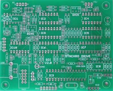
To generate the required synchro stator signals I developed a small 3.1" x 3.9" (80 mm x 100 mm) circuit board with analog
electronics and a local PIC processor. The processor receives the desired "setpoint" for the synchro and controls the analog stuff
to generate the needed stator amplitudes. As not all available I/O pins of the processor are used, those pins can be used for
other purposes, such as an output to control the on/off state of the ADI flags, or (with additional analog hardware) control the
deviation bar needle pointers and the Rate of Turn indicator (software generated PWM signal).
I dubbed the board "Synchro Drive Interface", abbreviated SDI.
The SDI needs two supply voltages, +5 Volt and -5 Volt. A dual symmetric 5 Volt power supply is needed for the analog circuits.
The PIC processor only needs +5 Volt. The SDI hardware design is as generic as possible, although many things can be realized in
the processor firmware. The SDI has an on-board 400 Hz sine wave oscillator which can be used if the synchro-based instrument
does not have its own power source with a 400 Hz oscillator (for example the small indicators such as HYDRAULIC
PRESSURE. If the instrument has its own 400 Hz source, the local 400 Hz oscillator on the SDI can be disconnected and the
400 Hz signal (derived) from the instrument can be used as input signal source to the SDI (jumper configurable).
The maximum amplitude of the three generated stator signals (and optional rotor signal) is limited to the power supply voltage minus the voltage drop of the OpAmp output. Further, it is important that the signals are not clipped by the OpAmps. To keep the signals clean the maximum amplitude is some 3 Volts. This is not sufficient to drive the stator connections of an instrument directly, so some form of external amplification is needed. By keeping the needed amplification external, the SDI board dimensions could be kept small and "generic". The external amplifiers depend on what instrument must be driven. 60 resistors, 30 capacitors, and 10 ICs all fit on the SDI board!
The SDI is originally developed as a "PHCC Daughter module", thus commands are sent to the SDI using the DOA interface. A USB interface is added to make the SDI available for pit builders using real instruments without "modifications", but who do not base the pit control on PHCC.
The ADI has two synchros, one for the roll movement of the sphere, and one for the pitch movement. As the SDI board support
only one synchro, two SDI boards are needed. Further, three analog signals are required that can be set to a voltage level ranging
from a negative value to a positive value. These are used for the horizontal and vertical deviation bar needle pointers and the
Rate of Turn indicator. Also, three digital signals are needed to move the flags out of view.
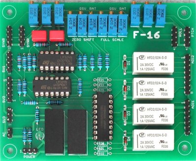
All these signals can be generated by the SDI hardware and specific firmware, but the required amplitude of the signals is not
in range of what the SDI board can deliver. So, an additional board is needed to increase the output voltage levels (and apply
a voltage level shift to the "analog" signals). This board uses OpAmps operating with +12 Volt and -12 Volt power supply to achieve
the required output voltages for the ADI. The PWM signal from the SDI board (high frequency on/off at 0 Volt / +5 Volt with variable
duty cycle) is level shifted to -2 Volt / +2 Volt and the amplified. Both level shift and amplification are adjustable with trim
potentiometers. This circuitry is used for the horizontal and vertical deviation bar needle pointers and the Rate of Turn indicator.
As the ADI itself needs +24V DC (besides the 115V AC 400 Hz), the SDI needs -5V / +5V, and the ADI Support OpAmps need -12V / +12V,
the ADI Support board also includes two DC/DC converters. With these converters only one simple +24V DC power supply is needed.
All other required voltages are generated "internally".
A driver IC "boosts" the +5 Volt on/off signals to +24V signals to drive the flags of the ADI.
Finally, the ADI Support board has 6 trim potentiometers to adjust the level of the stator signals (3 for roll synchro and 3 for
pitch synchro). This way the wiring is simplified. The stator signals from the two SDI boards are connected to the ADI Support
board, and these signals go to "stator output" connector pins via the trim potentiometers. These stator output connector pins
go to the external amplifiers that drive the ADI synchro stator inputs.
External stator amplifiers
When this project started I had little knowledge of the electronics inside the ADI. The instrument is way too expensive to open it
"to have a look". I assumed that the coils of the stators where directly connected to pins on the ADI connector at the rear side.
To drive a coil you need some sort of amplifier that can handle a fair output current. I reasoned that the stator coil can be
regarded as a coil (...) just as the coild in a loudspeaker. So, I built six 20W audio amplifiers which were cheap as kit on eBay
(less than 20 Euro per amplifier). The kit consists of one LM1875 amplifier IC, a PCB, its passive components and the bridge
rectifier with the big polarized capacitors. So, all that was needed additionally is a transformer with 2 secondary windings.
This setup works and I could drive the synchros nicely.
However, in the course of time I learned that the ADI has internal
amplifiers to drive the stator coils! The 20W external amplifiers that I used are not needed. All that is needed are signals of
sufficient amplitude. This can be realized using simple OpAmps. The space on the ADI Support board would probably have been a
problem to add six non-inverting OpAmps (plus 18 resistors), so these "amplifiers" are not on the ADI Support board. However,
the required power supply for these "external amplifiers" (-12 Volt and +12 Volt) can be obtained from the ADI Support board.
to be continued ...