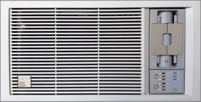
VAX 8200 (KA820 CPU)
VAX in 10.5" box |

|
INTRODUCTION
D|I|G|I|T|A|L 's VAX 8200 (introduced January 1986, code named "Scorpio") is the successor to the
widely installed and highly regarded VAX-ll/780. Providing the same power as its predecessor, the VAX 8200 is intended
as a department-level processor in office automation, commercial, and manufacturing applications. The four new models
(VAX 8200, 8300, 8500, and 8800) employ a new bus technology that promised to be a D|I|G|I|T|A|L
standard for the next decade. The VAX Bus Interconnect (VAXBI), a 32-bit synchronous bus, serves as a combination system
and I/O bus on the VAX 8200 and 8300, and as the I/O bus only on the 8500 and 8800. The last two systems employ a
high-speed memory interconnect as a system bus. The VAXBI features a maximum data transfer rate of 13.3MB per second and
provides connection for up to 16 VAXBI nodes. A VAXBI node is an interface that occupies one of 16 logical locations on
a VAXBI bus; it can be a mix of processors, memories, and adapters. Mass storage, bus, and communications adapters are
supported.
However, the VAX 8200 also supports the UNIBUS, so the UNIBUS peripherals used
by older VAX machines are supported. United by the VAX/VMS operating system, the VAX 8xx0s can be used as standalone
processors or can be configured in multi-node VAXclusters for enhanced power, mass storage, and availability. There is one
exception: the VAX8500 is is completely VAXBI based, thus no UNIBUS peripherals can be connected.
The relative speed of VAX systems is defined by the comparison of the speed of the VAX-11/780. The speed of the VAX-11/780
is defined as 1 VUP (Virtual Unit of Processing). Using this speed performance unity, the VAX 8200 is also 1 VUP. So, it
is not faster, not slower, but it is contained in a significantly smaller housing.
The VAX 8200 is the low end of the VAX 8000 family, which delivers VAX-ll/780 performance in one third the size at half
the price. According to D|I|G|I|T|A|L, the VAX 8200 complements the company's Micro VAX II, providing
users with expansion capabilities and features not available on that supermicro. The VAX 8200's CPU is similar in design to
that of the VAX-11/780, but is available on one 9-inch by 8-inch module, compared to 24 modules on the 11/780.
The VAX 8200 is upgradable to the 8300. The VAX 8300 uses the same technologies as the VAX 8200, but delivers higher
performance in compute-intensive applications by using tightly coupled dual 8200 processors. Each CPU contains an 8KB cache
memory; main memory is shared through the VAXBI bus. According to D|I|G|I|T|A|L, the 8300 provides up
to l.9 times the power (2 MIPS) of the VAX 8200 or VAX-ll/780, thus 1.9 VUP.
VAX 8200 CONSOLE SUBSYSTEM
The VAX 8200 (and VAX 8250, VAX 8300, VAX 8350) use a console subsystem. In general, the console subsystem is used to
examine and deposit data in memory or processor registers, stop the processor, and start the operating system. During
installation, the console subsystem is used to start the processor and monitor the process. The console subsystem
consists of the following:
- Console terminal (printer)
- Control panel
- Console diskette drive (RX50)
- Console command language
Control panel
The control panel is located in the lower right corner on the front of the computer and includes the following:
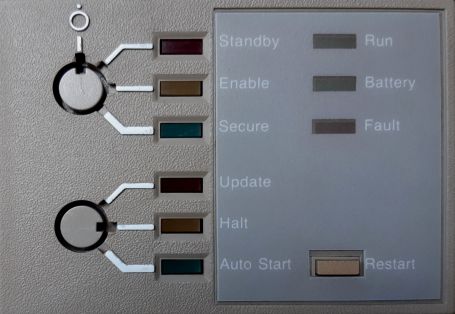
- 4-position keylock switch (upper)
- 3-position keylock switch (lower)
- 3 processor indicator lights
- Restart push button
- Upper keylock switch
- This switch has four positions. Use it to turn power on and off.
- Off
The upper keylock switch is set in the vertical position; there is no corresponding light. Turns off the power
in the entire system, including the battery backup unit.
- Standby
When the upper keylock switch is set to Standby, the corresponding indicator light glows red. Turns on the
power supply, the blower in the main unit, and system memory.
- Enable
When the switch setting is changed from Standby to Enable, the system self-tests run. When the upper
keylock switch is set to Enable, the corresponding indicator light glows yellow. Power is supplied to the entire
system. You can use the local console terminal in console mode to control the computer. If the lower keylock switch is
set to Auto Start, pressing the Restart push button reboots the system.
- Secure
When the upper keylock switch is set to Secure, the corresponding indicator light glows green. This setting
maintains power to the entire system and is used for normal operation. You cannot use the local console terminal in
console mode to control the processor. You cannot reboot the operating system by pressing the Restart push button.
- Lower keylock switch
-
This switch has three positions. Use it to enable and disable automatic restart after a power failure.
- Update
When the lower keylock switch is set to Update, the corresponding indicator light glows red. You can change data in
the Electrically Erasable Programmable Read-Only Memory (EEPROM) using the EEPROM Utility.
- Halt
When the lower keylock switch is set to Halt, the corresponding indicator light glows yellow. The system halts in
console mode. It displays the console-mode prompt (>>>) at the console terminal when power
is turned on after a power failure, after an error halt, or after a shutdown. This setting prevents booting of the
operating system when power is turned on.
- Auto Start
When the lower keylock switch is set to Auto Start, the corresponding indicator light glows green. Use this
setting for normal system operation to let the system reboot automatically when power is restored after a power failure,
after an error halt, or after a shutdown. If the upper keylock switch is set to Enable, pressing the Restart push
button reboots the system.
- Indicator lights
-
- Run
Glows when the processor is running and the console subsystem is in program mode.
- Battery
Shows the condition of the backup battery.
- Steady glow - The backup battery is fully charged.
- Slow flashing - The backup battery is charging itself.
- Quick flashing - The backup battery is supplying power to the system.
- No light - The backup battery unit is broken or is not present.
- Fault
Glows during self-tests and turns off when self-tests complete successfully. If the Fault light continues to glow after
self-tests complete, the self-tests have detected a hardware fault. If the Fault light glows after self-tests complete
and the VMS operating system boots, the system has detected a failure in a hardware module.
- Restart Push Button
-
The Restart push button is located on the lower right side of the control panel. The table details the functions of the
Restart push button, which depend on the positions of the upper and lower keylock switches.
Upper keylock
switch setting | Lower keylock
switch setting | Restart button
function |
|---|
| Enable | Auto Start | Runs self-test and reboots the VMS
operating system |
| Enable | Update or Halt | Runs self-test |
| Stand by or Secure | Any position | Does not function |
Console dual-diskette drive
The VAX 8200, VAX 8250, VAX 8300, and VAX 8350 computers have an RX50 dual-diskette drive. The dual-diskette drive is
located on the front of the computer. The dual-diskette drive is vertical on some processors and horizontal on others.
On a vertical drive, the left diskette drive is referred to as CSA1, and the right diskette drive as CSA2. On a
horizontal drive, the top diskette drive is referred to as CSA1, and the bottom diskette drive as CSA2.
The console dual-diskette drive holds RX50 diskettes. The console RX50 is the diskette that contains the BOOT58 program.
The BOOT58 program boots, or loads, the operating system into processor memory. It also is used to do the following tasks:
- Install updates
- Install optional software products
- Boot standalone BACKUP
- Store boot command procedures
When using the console dual-diskette drive as shown in the figure, you should be aware of the following:
- The light below the drive flashes when the floppy diskette is actually moving (being read or written to). If this
light is off, the drive is inactive. Never attempt to remove a floppy diskette when the light is flashing or glowing;
this damages the floppy diskette and might damage the drive.
- The light is off when the drive is empty. The only time you can remove a floppy diskette is when the light is off.
Inserting or Removing a Floppy Diskette
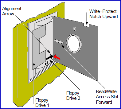 To insert a floppy diskette into console diskette drive CSA2, see the figure and follow steps 1 through 6.
To remove a floppy diskette, follow steps 1 through 3.
- Make sure the diskette drive is inactive. The light below the drive should be off. Never attempt to
open the diskette drive door if the light is glowing or flashing.
- Press the outer portion of the right door to open console diskette drive CSA2.
- If there is a diskette in the drive, remove it gently, taking care not to touch any exposed platter surfaces.
Place the diskette in a paper envelope.
- Remove the diskette to be inserted from its paper envelope; do not touch any exposed platter surfaces.
- Align the orange arrow on the diskette with the orange bar on the drive. Slide the diskette into the left-hand
side of the drive. (If the diskette is aligned improperly, the system displays an error message. If the system
displays an error message, remove the diskette, realign it, and reinsert it.)
- Close the diskette drive door.
Console command language
The console subsystem runs in two different modes: console mode and program mode.
- Console mode — When the console subsystem is in console mode, the VMS operating system is not running and
the console-mode prompt (>>>) is displayed. The CPU can be running or it can be stopped.
When the CPU is running, it responds to a limited number of commands. When the CPU is stopped, it responds to all
console-mode commands. To stop the CPU, press Ctrl/P at the console-mode prompt (>>>).
- Program mode — When the console subsystem is in program mode, the VMS operating system is running and the
dollar sign prompt ( $ ) is displayed. You can enter DCL commands, run programs, and receive system messages. If the
VMS operating system is running and you want to go to console mode, follow the shutdown procedure. You also can
press Ctrl/P to suspend program mode temporarily and go to console mode. To get back to program
mode, enter the CONTINUE command at the console-mode prompt (>>>).
Most Commonly Used Console Mode Commands
| Command | Definition |
|---|
| BOOT | Executes a console command procedure that loads a VAX software program
into memory. The console command procedure then transfers control to the program in memory and puts the console subsystem
in program mode. During the installation procedure, use the abbreviation, B, for the BOOT command. |
| CONTINUE | Changes from console mode to program mode. If the CPU clock
is operating when you type the CONTINUE command, the processor restarts execution of the halted program. If the CPU
clock is not operating when you type the CONTINUE command, the CPU clock starts as the console subsystem enters program mode. |
| DEPOSIT | Puts a value in the specified register or memory location. During
the installation procedure, use the abbreviation, D, for the DEPOSIT command. |
| EXAMINE | Displays a value in the specified register or memory location. |
| HALT | Resets the default console conditions after the processor stops. |
AVAILABLE DOCUMENTATION
See https://bitsavers.org/pdf/dec/vax/8200/