H.F. COMMUNICATIONS RECEIVER
|
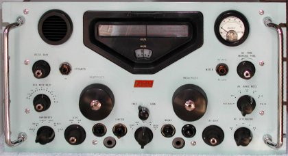
RA.17L H.F. COMMUNICATIONS RECEIVER |
|
| HIGHLIGHTS |
|
|
|
|
A Wadley loop drift-cancelling system, encompassing stages of the receiver up to a second mixer continuously corrects the frequency of the first v.f.o. (Megahertz Tuning); maintaining it to a degree equal to that of the internal 1 MHz crystal controlled frequency standard. Interpolation between 1 MHz points throughout the 1 MHz to 30 MHz range is accomplished by a second v.f.o. and mixer which is provided with a film-strip scale, the calibration of which can be checked at 100 kHz intervals. This second v.f.o. produces an output within the range 2 MHz to 3 MHz and is fully temperature compensated. The resulting overall frequency stability (after warming-up) is less than 50 Hz drift per hour, under constant environmental conditions. The utilization of modern electronic bandswitching methods eliminates multi-contact switches and wiring in the r.f. circuits, thus enhancing receiver reliability.
Triple frequency conversion, employed within the receiver, assures excellent image performance coupled with spurious-free operation through careful choice of oscillator frequencies and specially engineered filters.
The RA.17 is approved and used by the Armed Services and by major communications and broadcasting authorities in nearly every country in the world. All components are selected for dependable performance in all climates and are type-approved for military use.
 The r.f. stage of the RA.17 is preceeded by an attenuator network and has switched choice of wideband input or
double-tuned pre-selection.
The r.f. stage of the RA.17 is preceeded by an attenuator network and has switched choice of wideband input or
double-tuned pre-selection.
The amplified input signal is subsequently mixed in M1 with a variable frequency
oscillator (VFO1) to produce a wideband first i.f. output centred on 40 MHz.
|
| Click the image for a better detailed block diagram |
The output of VFO1 is also mixed in M4 with harmonics (up to 32nd) generated from a 1 MHz crystal oscillator. The output circuit of M4 limits the useful settings of VFO1 to intervals of 1 MHz, that is when VFO1 minus a harmonic of 1 MHz gives a product of 37.5 MHz from M4. The output from the 37.5 MHz filter and amplifier circuits is mixed with the first i.f. in M2 to produce a wideband second i.f. from 2 MHz to 3 MHz.
This ingenious arrangement ensures that, if VFO1 drifts and so creates a change in the first i.f., an equal change is caused in the 37.5 MHz output and the drift is cancelled in M2. Tha stability of this frequency changing system is therefore that of the 1 MHz crystal. VFO1 is set by the "megahertz" dial of the receiver and acts as an electronic bandswitch.
The signal is then accepted by a conventional superheterodyne receiver tuned over the range 2 to 3 MHz by VFO2. This interpolation receiver employs a film scale 5 ft. long, calibrated at each kilohertz, coupled to VFO2 and a tunable band-pass filter. VFO2 includes a special coupling circuit to simplify dual diversity operation.
The complete absence of mechanical bandswitching and multiple wiring in both VFO circuits together with well-designed temperature compensating circuits ensures very high re-setting accuracy and stability.
The final i.f. chain operates at 100 kHz and incorporates filters giving a choice of six bandwidths. A built-in calibrator is provided for setting the film scale cursor exactly to each 100 kHz point. Additional facilities include a buffer amplifier giving an i.f. output at 100 kHz and an a.f. amplifier supplying an independent output for 600-Ohm line circuits.
 more to be added
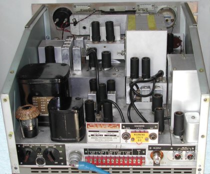
If the RA.17 receiver was built for the English army, it has a small black type label mounted on the front just above the escutcheon of the kHz scale. The label indicates the weight in Lbs, a NATO stock number and a year code that consists of 2 letters. Use the table to determine in what year and month your receiver was built.
| first letter - YEAR | second letter - MONTH | ||||||
|---|---|---|---|---|---|---|---|
| N | 1956 | U | 1963 | A | January | G | July |
| O | 1957 | V | 1964 | B | February | H | August |
| P | 1958 | W | 1965 | C | March | I | September |
| Q | 1959 | X | 1966 | D | April | J | October |
| R | 1960 | Y | 1967 | E | May | K | November |
| S | 1961 | Z | 1968 | F | June | L | December |
| T | 1962 | ||||||
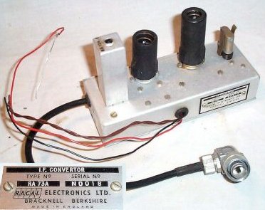
A buffer amplifier, type MA.251, is added to the RA.17. This buffer amplifier is a small chassis with one tube, but
is very difficult to obtain.
The schematic diagram shows buffer amplifier a suggested by RACAL.
Notes :