|
RK06 / RK07 removable hard disk drive |
| RK611 controller |
Direct jumps to:
If you want to print this page on A4 or Letter format, set the scaling in the printer driver to 80%.
INTRODUCTION
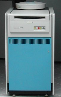 Besides the RL01 and RL02's that I have connected to my PDP-11/34C, I have also hooked up two RK07 drives to that system.
This enables several media conversion options in my computer museum.
Besides the RL01 and RL02's that I have connected to my PDP-11/34C, I have also hooked up two RK07 drives to that system.
This enables several media conversion options in my computer museum.
The RK06 and RK07 are moving head disk drives. The drive uses a top-loading, dual-platter removable disk cartridge,
RK06K or RK07K. Note that the RK06K disk cartridge can not be used on an RK07 drive, nor an RK07K cartridge on an RK06
drive.
An RK06K disk cartridge can hold some 13 Mbytes of data, whereas an RK07K disk cartridge can hold twice as many: 26 Mbytes.
The RK06/RK07 is called a disk subsystem as the drive is a free-standing device. The disk subsystem connects to the RK611
controller which is a dedicated backplane, called a system unit, that holds several boards. The RK611 is installed in the
processor or expansion box that connects to the processor via the UNIBUS. Up to 8 disk subsystems can
be daisy-chained to one RK611 controller and the controller supports any mix of RK06 and RK07 disk drives.
Dual access operation is a hardware option to enable the disk subsystem to be accessed through two different controllers.
The two RK611 controllers can be connected to two different CPU's.
AVAILABLE DOCUMENTION
- Manuals
-
- RK06/RK07 Disk Drive User's Manual (EK-RK067-UG-001)
- RK06/RK07 Disk Drive Service Manual (EK-RK067-SV-003)
- RK06/RK07 Disk Drive Technical Description Manual (EK-RK067-TD-001)
- RK6/7 FTB Operating and Service Manual (EK-RK67F-OP-001)
- RK611 Controller Technical Manual (EK-RK611-TM-003)
- Engineering drawings
-
- RK07 Disk Drive Field Maintenance Print Set MP00576
- RK611 Field Maintenance Print Set MP00105 (rev. B)
Back to top
GENERAL DRIVE INFORMATION
| | RK06 drive | RK07 drive |
|---|
| Rotation speed | 2400 rpm |
Latency
average
maximum |
12.5 ms
25 ms |
Seek time
average
maximum |
38 ms
75 ms |
36.5 ms
71.0 ms |
| Start/stop time | 60 sec max, 30 sec nominal |
|
The input power at 60 Hz for a single access drive is 450W nominal, 500W max; at 50 Hz the input power is 500/550W.
For dual access drives the input power increases with 50W.
The start current is according to the documentation as follows :
- 115V/60Hz : 10.5 A rms
- 230V/60Hz : 5.3 A rms
- 115V/50Hz : 11.0 A rms
- 230V/50Hz : 5.5 A rms
Add 0.8 A for dual access configured drives. |
The connection cable between the drive cabinet and the system cabinet is available in 4 lengths.
The option numbers are 70-12292-08, 70-12292-15, 70-12292-25, and 70-12292-40.
The last two digits define the length of the cable in [ft].
The total length of cabling from the RK611 controller upto the last drive must not exceed 100 ft. (30.48m).
Inside the disk drive is a small card cage that houses the drive logic modules.
 |
 |
Only the last 3 slots (slots 6, 7, and 8) contain different card for the RK06 or RK07 drive.
RK06 drive slot 6, 7, 8
(6) Servo Control Logic - M7707
(7) Servo Analog PCB - M7729
(8) Track Position Sensor - M7708
RK07 drive slot 6, 7, 8
(6) Servo Control Logic - M7907
(7) Servo Analog PCB - M7906
(8) Track Position Sensor - M7908
|
| RK06 Card Cage | RK07 Card Cage | |
|---|
HOW TO USE THE RK06/RK07 DRIVE

Lift the top cover, put the disk cartridge in the drive with the cartridge cover on top of the disk, and close the top
cover.
Push the "RUN/STOP" button; the light extinguishes.
The disk drive starts to spin up the platters inside the disk cartridge.
After you load the disk you must wait for some 30 seconds before you can access the data on the disk because the disk must
accelerate to 2400 revolutions per minute. When the platters reached the correct speed the drive becomes "READY".
Now you can read from and write to the disk.
To remove the disk cartridge push the "RUN/STOP" button; the disk spins down. This takes about 30 seconds.
Locking mechanisms prevent you from trying to take the disk cartridge out of the drive before the disk is spun down.
When the platters are no longer rotating the light in the "RUN/STOP" button is turned on and you can lift the top cover
to remove the disk cartridge from the drive.
The ACCESS A ENABLE and ACCESS B ENABLE switches are alternating pushbuttons.
If Port A is configured for single access (the M7706 Interface and Timing module is installed in slot 3 of the drive
card cage) and the ACCESS A ENABLE switch is initially depressed, bidirectional communication with
the controller is enabled via Port A. When the drive is selected by the controller the SELECT A
indicator is illuminated.
If Port B is configured for single access (the M7706 Interface and Timing module is installed in slot 2 of the drive
card cage) and the ACCESS B ENABLE switch is initially depressed, bidirectional communication with
the controller is enabled via Port B. When the drive is selected by the controller the SELECT B
indicator is illuminated.
When both ACCESS A ENABLE and ACCESS B ENABLE switches are depressed on a dual
access drive, arbitration logic will determine, on a priority basis, which port (A or B) will be accessed by its
associated controller.
RK06/RK07 DISK CARTRIDGES
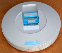
The RK06K and RK07K disk cartridge look very similar to the cartridges used on the RL01/RL02 drives, but the RK06K/RK07K
cartridges are higher as they contain two platters. The two surfaces of the upper platter are used to store (user) data
on, the bottom surface of the lower platter stores also user data, but the top surface of the lower platter provides
positioning signals for the servo to position the read/write heads and timing signals for data transfer
synchronization.
These disk cartridges are factory preformatted. When you format the disk you only initialize the data tracks.
Special equipment is needed to write the servo tracks.
The RK06 and RK07 disk look the same, only the color of the label is different: RK06 disks have a grey label,
RK07 disks have a blue label, just as the RL01/RL02 disk cartridges. The disk cartridge exist in two versions: with
the suffix "-DC" and "-EF". The latter suffix stands for "Error Free"; this -EF version is more expensive.
Sometimes the packs have a shock watch indicator glued on them, near the grip handle. Normally its small tube is
colorless, but when the pack has been dropped or subjected to a shock the indicator is turned red. When this has happened
it is a strong indication to consider some caution when using the disk cartridge in a drive. When the platters inside are
distorted by the shock, a head-crash can occur. If you need to extract the data off the disk cartridge, load the
cartridge in the drive and press the "LOAD" button; the disk starts to spin up. Holding your hand on the drive front
while spinning up could give you a feel of unusual vibrations. Keep your finger on the "LOAD" button! After some 30-40
seconds the heads loads. When you hear unusual sounds ('pinging') you better immediately press the "LOAD" button again!
The heads will disengage preventing damage to them. Try to copy the data off the cartridge while keeping your finger on
the "LOAD" button.
What feels and sounds 'normal' is something you get used to over time.
|
| Data storage capacity |
|---|
| |
RK06K | RK07K |
|---|
| Number of platters | 2 |
| Number of data surfaces | 3 |
| Number of cylinders/cartridge | 411 | 815 |
| Number of tracks/cylinder | 3 |
| Track density (per inch) | 192.3 | 384.6 |
Number of sectors/track
18-bit words
16-bit words |
20
22 |
| Number of words/sector | 256 |
Formatted capacity
18-bit words
16-bit words |
6.3 million
6.9 million |
12.6 million
13.8 million |
The disk cartridge has a nominal diameter of 355 mm (14").
|
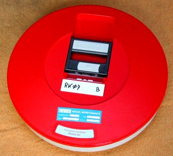
A special cartridge is the RK07K-AC "Alignment Disk" cartridge.
This cartridge has a clearly visible different color!
A similar disk, RK06K-AC (also RED) exists for the RK06 drive.
The disk is used in the alignment procedure of the RK07 drive.
More information will follow ...
RK611 INTERFACE - DRIVE CONNECTION
 The connection to the drive consists of the following parts.
- flatcable from the controller module (BERG connector) to the bulkhead in the rack.
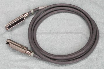
- round cable (BC23Z-xx or 70-12292-xx) from bulkhead to the first drive IN connector. This cable
is also used to connect all other RK06/RK07 drives (max 8 drives, and RK06 / RK07 can be mixed). The "xx" in the cable
number stands for the length in feet. A common value is 10. The connector has 40 pins.
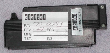
- terminator on the last drive in the chain, on the OUT connector.
The picture at the right shows a 10-feet cable with metal caps for the connector.
The cable also exists with black plastic caps.
A small black "knob" on top of the end of the connector latches the connector to its counterpart on the drive or the
bulkhead by rotating it 90 degrees.
top view
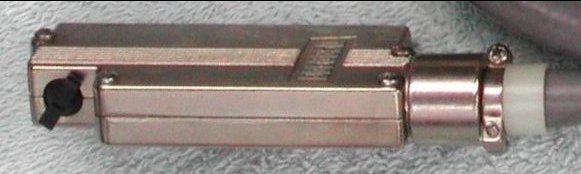
pin view
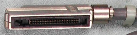
terminator
 |
Note that this cable looks like the cable to connect RL01/RL02 drives.
However, the part number for the RL01/RL02 cable is 70-12122-xx, uses the same connector, but
not all pins are actually connected in the cable! So, you can use the RK06/RK07 drive cable to connect RL drives,
but you can not use the RL01/RL02 drive cable to connect RK06/RK07 drives.
The terminator used for the RL01/RL02 and the RK06/RK07 drives is identical.
|
RK611 UNIBUS INTERFACE
The RK611 backplane is a 9-slot system unit that holds the five boards of the RK611 controller.
The first 3 slots can be used as SPC slots to install Small Peripheral Controllers.
One module can only be quad height, the other two can be quad or hex height modules.
note: If slot 1, 2, or 3 does not hold a SPC you must install a G727 grant card in position D.
Slot 1, position A-B connects to the UNIBUS (BC11A cable, M9202 module bridge).
Slot 9, position A-B connects either to the next system unit or has a UNIBUS terminator installed.
| Power requirements RK611 System Unit |
|---|
| + 5 Vdc +/-5% | @ 15 A. |
| +15 Vdc +/-5% | @ 175 mA. |
| -15 Vdc +/-5% | @ 400 mA. |
The default device base address is 777440, and interrupt vector is 000210. These numbers are of course octal, and both
are switch selectable. The interrupt priority is plug-selectable and the default is Level 5. Note that the RK611 base
address overlaps with a register of the RC11 Disk subsystem.
| FCO M7901-003 | | |
|---|
- On side 2, the etch at pin E11-11 is cut
- On side 2, the etch at E12-5 is cut
- On side 1, a wire is added, connecting E11-10 to E11-11
- On side 1, a wire is added, connecting E12-5 to E17-2
| |
For RK07 installations, the M7901 (Registers) in the RK611 controller must be above Etch E.
If not, FCO no. M7901-003 must be added.
|
If the RK611 controller is to be connected to a PDP-11/40 (or PDP-11/35) system, you must remove the jumper W5 on
the M7234 CPU module.
This jumper must be removed to successfully run the RK06 or RK07 diagnostics.
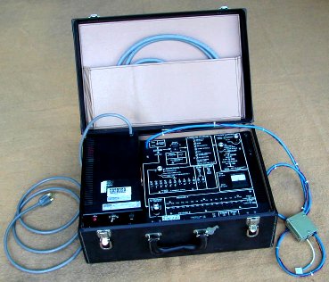
RK06/RK07 Field Test Box
RK611 CONTROLLER DIAGNOSTICS
|
The RK611 UNIBUS interface has the following diagnostics.
| «-»
| ZR6A(x) | Diskless Controller Diagnostic #1 |
| «-»
| ZR6B(x) | Diskless Controller Diagnostic #2 |
| «-»
| ZR6C(x) | Diskless Controller Diagnostic #3 |
| «-»
| ZR6D(x) | Diskless Controller Diagnostic #4 |
| «-»
| ZR6E(x) | Diskless Controller Diagnostic #5 |
You must stop the processor manually to terminate ZR6A or ZR6B, and restart XXDP (152010). The diagnostic tests ZR6C
(run time 10 to 12 minutes), ZR6D (3:15 minutes), and ZR6E (4 minutes) can be stopped by entering
^ C (Control-C).
These will print a message "stopped" and then you can restart XXDP.
The following diagnostics are for the disk drive / cartridges.
| «-»
| ZR6H(x) | Disk Drive Diagnostic #1 |
| «-»
| ZR6I(x) | Disk Drive Diagnostic #2 |
| «-»
| ZR6K(x) | Functional Controller Test |
| «-»
| ZR6L(x) | Drive Formatter |
| «-»
| ZR6M(x) | Dynamic Test part #1 |
| «-»
| ZR6N(x) | Dynamic Test part #2 |
| «-»
| ZR6P(x) | Performance Exerciser |
| «-»
| ZR6Q(x) | Compatibility Test |
| «-»
| ZR6R(x) | User Defined Test |
The (x) represents the version.
This is a single letter for the revision level, and one single digit for the patch level.
|
|
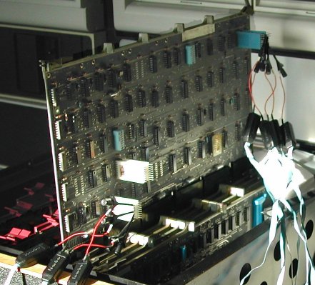 Here you see the five boards of the RK611 controller, with the "UNIBUS INTERFACE", M7900, on extenders
for good access to the signals. My controller did not pass the first diagnostic (ZR6A). For reference, this was the XXDP output.
Here you see the five boards of the RK611 controller, with the "UNIBUS INTERFACE", M7900, on extenders
for good access to the signals. My controller did not pass the first diagnostic (ZR6A). For reference, this was the XXDP output.
  .R ZR6A??.???
  ZR6AD0.BIN
  RK611 DISKLESS DIAGNOSTIC: PART 1 CZR6AD0
  @
  ATTEMPTING TO CLEAR CS1 WITH A SUB CLEAR
  BUS ADD  INCORRECT
  TEST     ERROR
  NUM      PC
  000041   033024
    PREV     EXPECT   ACTUAL
    VALUE    VALVE    VALVE
    013776   000200   100200
The problem was solved when I removed the flat cable connected to the "DRIVE INTERFACE" module, M7904!
The "official" cable from the module to the bulkhead is a BC06R, but I did not have the field maintenance print set at the
time I installed the RK611. I installed a simple flat cable without shielding and approximately 6 meters long ... That
cable probably picked up noise and caused error signals to be asserted in the RK611. After I installed the correct cable,
a BC06R-6, all the controller diagnostics (ZR6A thru ZR6E) ran without reporting errors.
Lesson learned: make sure you have all the correct parts, including the required cables.
You can have confidence in the controller when each of the 5 diagnostics has run two passes without error reporting.
The first diagnostic with the drive (ZR6H) also reported errors. It turned out that the drive is OK, but the cartridge is not!
The most relevant registers to look at in de diagnostic print out are the following.
- RKCS1 - Control and Status Register 1
 This is the first register to examine. Bit 15 CERR (Combined Error) is set when any error occurred. If this bit is clear there
are no error conditions, but if it is set you must check others bits in this and other registers. The error indicator
bits in this register are the following.
This is the first register to examine. Bit 15 CERR (Combined Error) is set when any error occurred. If this bit is clear there
are no error conditions, but if it is set you must check others bits in this and other registers. The error indicator
bits in this register are the following.
- CTO [11] - Controller Time Out
- DTC PAR [13] - Drive-To-Controller Parity Error
- RKCS2 - Control and Status Register 2
 This register has several error indicator bits that do not necessarily have their cause in the RK611 controller or the
RK07 drive. Examples are bit 11 NEM - Non-Existent Memory, and bit 12 NED - Non-Existent Drive. These errors are probably caused
by programming faults, but they can be caused by hardware problems, so always check all error flags! The subsystem specific error
indicator bits in this register are the following.
This register has several error indicator bits that do not necessarily have their cause in the RK611 controller or the
RK07 drive. Examples are bit 11 NEM - Non-Existent Memory, and bit 12 NED - Non-Existent Drive. These errors are probably caused
by programming faults, but they can be caused by hardware problems, so always check all error flags! The subsystem specific error
indicator bits in this register are the following.
- UFE [08] - Unit Field Error
- MDS [09] - Multiple Drive Select
|
- WCE [14] - Write Check Error
- DLT [15] - Data Late Error
|
- RKER - Error Register
 The Error Register shows the error status of the selected drive. Note that the bit settings are only valid if SVAL [bit 15]
in the Drive Status Register is set. All of these bits are important, but there are a few that can be set not because of
the drive, but because of the state of the cartridge.
The Error Register shows the error status of the selected drive. Note that the bit settings are only valid if SVAL [bit 15]
in the Drive Status Register is set. All of these bits are important, but there are a few that can be set not because of
the drive, but because of the state of the cartridge.
- SKI [01] - Seek Incomplete
- ECH [06] - Error Correction Hard
|
- BSE [07] - Bad Sector Error
- OPI [13] - Operation Incomplete
|
- RKDS - Drive Status Register
 As the register name indicates, the bits show the status of the drive. Noteworthy here are the following bits.
- DRA [00] - Drive Available
- ACLO [03] - Drive AC Low
- SPLS [04] - Speed Loss
|
- DRDY [07] - Drive Ready
- SVAL [15] - Status Valid
|
There are several other registers, and depending the execution of the diagnostic they can hold information that might help
you locate the fault source. The bits that I mentioned here helped me to get the RK07 up and running, but that does not mean
that you can ignore the other bits if your subsystem shows a problem.