 This page shows my PDP-11/34C system. It is housed in just two H960 industrial 19" cabinets
(from DIGITAL). One cabinet contains the PDP-11/34C system and a few peripheral devices. That cabinet also houses
a PDP-11/10 with a TU60 DECasette. The other cabinet contains more peripheral devices like disk drives and the BA11-K
expansion box.
This page shows my PDP-11/34C system. It is housed in just two H960 industrial 19" cabinets
(from DIGITAL). One cabinet contains the PDP-11/34C system and a few peripheral devices. That cabinet also houses
a PDP-11/10 with a TU60 DECasette. The other cabinet contains more peripheral devices like disk drives and the BA11-K
expansion box.
The PDP-11/34 was the most succesful PDP-11 in terms of unit volume and was introduced in 1975.
The PDP-11/34 is positioned as a mid-range system and featured a central processor so compact that the entire
CPU logic fits on 2 circuit boards.
This PDP-11/34C is the 10˝" height (BA11-K box) version. All the boards are seated vertically next to each other.
The BA11-K box houses the H765 power supply. As the BA11-K box was too small to accomodate all the system units, an
additional BA11-K expansion box is added to the system. A system unit is a backplane (4 or 9 slots) in which you can
install circuit boards, called modules. This system also uses an 861 AC Power Controller.
There is also a 5Ľ" height (BA11-L box) version in which the boards are placed horizontally.
The smaller BA11-L box has an internal H777 power supply and cannot accommodate as many boards as the BA11-K box.
Note.
The standard system designator is PDP-11/34A. That is how I got this system.
But I added the KK11-A Cache option, and DEC called this configuration officially PDP-11/34C. See "Computer Engineering",
Bell, Mudge and McNamara, © 1978, page 408. In the chart of "Characteristics of PDP-11 Models and Techniques Used to Span
Cost and Performance Range", the 11/34 is listed on one line, and the 11/34C on an other line. Thanks for
this information, Lyle.
Jumps within this page are the following:
GENERAL SYSTEM INFORMATION
|
## picture of complete PDP-11/34A system (to be added) ##
|
- System history
-
This PDP-11/34A has been used at the Technical University "Twente", in the eastern part of the Netherlands.
I got it from a group of students. They 'sold' it to me for a crate (this is 24 bottles) of beer. With it came
a TU56 dual DECtape drive! Unfortunately, the TC11 controller was in an other cabinet, that the students did not
think of being important ...
I want to connect the TU56 to the PDP-11/35 system from a more historical point of view.
- System description
-
My PDP-11/34A consists of the basic KD11-EA 11/34A Central Processing Unit, and is equiped with all PDP-11/34A
available processor options. The processor boards and the options are all described on the page CPU information.
This is a subfolder of the PDP-11/34A folder. The PDP-11/34A processor options are :
- KK11-A Cache Memory
- FP11-A Floating Point Processor
- KY11-LB Programmer's Console
The system is completed with the following peripherals :
- disk storage units
- magnetic tape storage units
- communication devices and interfaces
- line printer LA210
- monitor console VT102
- DELUA Ethernet network interface
|
|
When you click on the link you can read more about the specific peripheral device. All peripherals that I have
are also described in the 'subfolder' peripherals, on which you can click in the navigation section at the left.
To return to this location, click on the text 'PDP-11/34A' after the first subfolder.
I hope to add an original DIGITAL paper tape reader/punch unit (PC11) to this system in the future.
So, if you have one, and you want to get rid of it (...), please contact me.
11/34 and 11/34A processor differences
module | PDP-11/34 | PDP-11/34A |
|---|
| identification | KD11-E | KD11-EA |
| data path | M7265 | M8265 |
| control | M7266 | M8266 |
| SACK time-out | M8264 | --- |
|
The KD11-E processor consists of three boards, whereas the KD11-EA has only two
boards. Both processor boards of the 11/34 and the 11/34A are multi-layer and are hex-height modules.
Extended Instruction Set (EIS) is a standard feature for the KD11-E(A). The
KD11-E(A) also contains memory management logic to extend the memory space from 28k to 124k word.
|
|
The 11/34A was developed to add the floating point option FP11-A and includes the SACK time-out circuitry and the
required connections for the floating point option. Also, the power supply of the PDP-11/34A has more output Amps to
support the FP11-A.
|
11/34 PROGRAMMER's SYSTEM CONSOLE
The PDP-11/34 has two different consoles, the basic console KY11-LA, and the more elaborate console KY11-LB.
The KY11-LA console has just two switches, a rotary 3-position switch and three indicators.
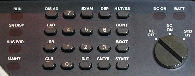
The optional KY11-LB has a 20-pushbutton keypad, six indicator LED's, a six digit 7-segment display for address and data and a DC power switch.
The KY11-LB interfaces to the UNIBUS via the quad-height module M7859. This board must be installed in the processor backplane.
- KY11-LB indicators
The indicators BATT, DC ON and RUN function in the same manner as described in the next paragraph, KY11-LA indicators.
| KY11-LB programmer's console indicators |
|---|
six 7-segment
displays | The 7-segment display represents the current address or the contents of the current address.
Each segment of the display shows an octal digit (0-7). Six digit numbers are generated as octal digits and are entered from the right and left-shifted.
|
| SR DISP | Switch Register Display - Indicates, when on, that the contents of the Switch Register (address 777570) is displayed. |
| MAINT | Maintenance - Indicates, when on, that the console is operating in maintenance mode. |
| BUS ERR | Bus Error - Indicates, when on, that an examine or a deposit resulted in a SSYN timeout, or that HALT GRANT was not received after a HALT REQUEST was issued.
Note: this indicator reflects a bus error by the console only. The indicator does not reflect bus errors due to other devices such as the processor |
- KY11-LB pushbutton keypad
The rotary 3-position switch functions in the same manner as described in the next paragraph, KY11-LA switches.
| KY11-LB programmer's console keypad |
|---|
| 0,1,2,3,4,5,6,7 | Allows the operator to enter octal data into the display.
|
| LSR | Load Switch Register - A copy of the contents of the display is stored in UNIBUS address 777570. |
| LAD | Load Address - The contents of the display becomes the current address. The display is cleared when LAD is pressed. |
| DIS AD | Display Address - The current address is displayed. The next examine or deposit will occur at the address displayed. |
| CLR | Clear - The display is cleared in preparation for entry of new data via the number keys. |
| EXAM | Examine - A copy of the data contained in the location specified by the current address is shown in the display. This key is operative only when the processor is halted. |
| DEP | Deposit - A copy of the data being displayed is transfered to the location specified by the current address. This key is operative only when the processor is halted. |
| CNTRL | Control - The Control key is used in conjunction with other keys to provide certain functions. The requirement of having both CNTRL and the second key pressed at the same time prevents accidental use of these functions. |
| CNTRL key controlled functions |
|---|
| INIT | Initialize - Causes BUS INIT L to be generated for 150 mSec. This key is operative only when the processor is halted. |
| HALT/SS | Halt / Single Step - Halts the processor if the processor is running. To single step the processor, halt the processor, then press the HALT/SS key without pressing the CNTRL key. After a halt, the display will contain the contents of R&, the program counter. |
| CONT | Continue - Allows the processor to continue from a halted state using its current program counter. The contents of the Switch Register is displayed. |
| START | Start - This key is operative only if the processor is halted. The function causes the program counter (R7) to be loaded with the current address. BUS INIT L is then generated and the processor is allowed to run. Switch Register contents is then displayed. |
| BOOT | Boot - Causes the M9312 (or other bootstrap/terminator) to be activated if present in the system. Console will boot only if the processor is halted. |
| button 7 | When keypad button #7 and CNTRL are both pressed, the current address plus the value presently being displayed plus 2 are added together. The result is then displayed. This function allows the console to calculate the correct offset address when mode 6 or 7, register 7 instructions are encountered. The required index must be in the display so that when the keys are pressed, the index will be added to the PC+2. The offset address is the displayed. |
| button 6 | When keypad button #6 and CNTRL are both pressed, the contents of the Switch Register are added to the value presently being displayed. The result is then displayed. This function allows the console to calculate the correct offset address when mode 6 or 7 instructions that do not use register 7 are encountered. To implement this function, it is easiest to put the index in the Switch Register, the examine the general register that contains the base address, thereby placing the base address in the display. Then, when the #6 key and CNTRL are both pressed, the index and base address will be added and the correct offset address will be displayed. |
| button 1 | Maintenance Mode - This key combination puts the console in maintenance mode. When the console is in maintenance mode, normal console mode keypad functions are not available. The CLR key causes the console to exit from maintenance mode and enter console mode via a processor halt. |
- KY11-LA indicators
| KY11-LA basic console lights |
|---|
| BATT | off | battery voltage is below the minimum level required to maintain the contents of the MOS memory, or the battery is not present in the system |
slow flash
(1 flash per 2 sec) | battery is charging and the voltage is above the required level to maintain the contents of th MOS memory if power is removed |
fast flash
(10 flashes per sec) | primary power is lost and the battery is discharging while maintaining MOS memory contents |
| on | battery is present and fully charged |
| DC ON | on | DC power is applied to the logic.
It does not imply that the power is within the required levels |
| off | DCpower is off |
| RUN | on | indicates either:
1. - processor is executing, or
2. - processor is attempting to run, but is disabled due to a system failure |
| off | processor is halted |
- KY11-LA switches
| KY11-LA basic console switches/buttons |
|---|
3 position
rotary switch | DC OFF | DC power removed from the system, contents of MOS memory are lost and fans are off. NOTE: this does not remove AC power!
|
| DC ON | power is applied to the computer system |
| STNDBY | DC power to the computer is off, but DC power is applied to MOS memory. |
HALT/CONT
(2 position toggle) | HALT | program is stopped |
| CONT | program is allowed to continue |
BOOT/INIT
(spring-action, momentary) | INIT | - if HALT/CONT is in the HALT position, only the processor is initialized and peripheral device registers are not cleared
- if HALT/CONT is in the CONT position, the processor is initialized, peripheral device registers are cleared and the bootstrap program is executed
|
THIS 11/34A SYSTEM CONFIGURATION

A backplane that supports a complete function is called a system unit. The DD11-CK and the DD11-DK are examples
of general purpose system units. They can have several boards with different functions in its backplane.
Every system unit has an UNIBUS-in and a UNIBUS-out slot. The 'out'-section connects to the 'in'-section of
the next system unit with a "module bridge" connector.
The DD11-PK basic PDP-11/34 processor system unit has 9 slots of which the first two are dedicated to the processor.
As this system unit is the first in a PDP-11/34A, there is no UNIBUS-in. That is actually on the processor board in
slot #1 (M8266, datapaths module). The last (9th) slot of this system unit has the UNIBUS-out and a so-called SPC slot.
SPC stands for 'Small Peripheral Connection'. This SPC-slot commonly holds the interface card to connect the system
console.
The DD11-DK is a 9 slot general purpose back plane. In my configuration this system unit holds the
following modules.
- RL11 (M7762) interface for the RL drives
- RX211 (M8256) interface for the RX02 floppy drives
- MS11-LD (M7891-DF) 128-Kword 18-bit parity MOS memory
- DL11-W (M7856) serial line unit
- DELUA (M7521-AA) Ethernet interface
The last backplane is the TMB11 option. This is a 4-slot dedicated system unit for the support of the TU10 or
TS03 tape drive. The last slot, position A-B holds the UNIBUS terminator (M9302) for a single BA11 box PDP-11/34(A) system,
but in my PDP-11/34, a BC11-A cable connects to a second BA11 box. This BA11 expansion box holds the RK611 controller to
which two RK07 removable pack disk drives are connected.
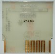
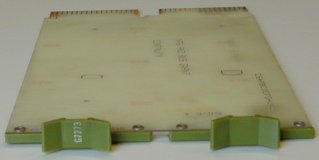 All slots that are not used (in the general purpose backplanes) must have a grant-continuity card (G727A) in position D to
continue the UNIBUS. An other important connection which can cause a lot of problems is the connection between pins CA1 and CB1
in position C. These two pins carry the NPG (Non Processor Grant) signal, and acts as a "handshake" between two devices for
a data transfer (nowadays called DMA, Direct Memory Access). Normally the connection between these two pins is shorted
by a wire on the backplane. When you install a module that does DMA (for example the RL11 controller) you must cut the wire
between CA1 and CB1 in position C. If that module is removed, you must restore the connection between these two pins on the
backplane, or install an other option that either uses DMA or connects these pins (in-out of the daisy-chain), or install a
grant module G7273 in the free slot, positions C-D. The G7273 has the four connect-throughs of the G727A and connects CA1 to
CB1 to continue the NPG daisy-chain on the backplane.
All slots that are not used (in the general purpose backplanes) must have a grant-continuity card (G727A) in position D to
continue the UNIBUS. An other important connection which can cause a lot of problems is the connection between pins CA1 and CB1
in position C. These two pins carry the NPG (Non Processor Grant) signal, and acts as a "handshake" between two devices for
a data transfer (nowadays called DMA, Direct Memory Access). Normally the connection between these two pins is shorted
by a wire on the backplane. When you install a module that does DMA (for example the RL11 controller) you must cut the wire
between CA1 and CB1 in position C. If that module is removed, you must restore the connection between these two pins on the
backplane, or install an other option that either uses DMA or connects these pins (in-out of the daisy-chain), or install a
grant module G7273 in the free slot, positions C-D. The G7273 has the four connect-throughs of the G727A and connects CA1 to
CB1 to continue the NPG daisy-chain on the backplane.
If one slot is left open, the system will hang. This is a common error cause when a board is removed that used DMA.
You can recognize the situation of a broken NPG chain because the "RUN" light will always stay on, and the
system will not 'listen' when you try to halt the system (when you press "CNTRL" and "HLT/SS"
at the same time).
All the system units are interconnected with a M9202 module bridge.
PDP-11/34A PROCESSOR (and options) POWER REQUIREMENTS
The DD11-PK processor backplane can hold the following (processor-specific) modules.
- The two basic PDP-11/34A processor boards, M8265 and M8266
- The KY11-LB programmer's console interface board, M7859
- The FP11-A floating point processor option board, M8267
- The KK11-A cache memory option board, M8268
These boards are processor specific, but the slots in the DD11-PK backplane are not dedicated, except the first two slots
for the basic PDP-11/34A processor. Hence, the slot positions 3 thru 9 commonly hold the following options.
- a console interface board and real-time clock, DL11-W, M7856 (quad, SPC)
- interface for the RX02 floppy drive, RX211, M8256 (quad, SPC)
- interface for the RL01/RL02 disk drive, RL11, M7762 (hex)
- one or more MOS memory boards, MS11-L, M7891 (hex)
Slot 9, positions A-B are the UNIBUS-out connectors, and the module bridge M9202 is used to connect to the next System Unit.
When you add a processor option to the DD11-PK backplane, you must do some power requirement calculations to prevent an
overload on the H7441 module that powers this backplane with 5 Volts (max 32 Amps!). Possibly, you must move one of the
non-processor-specific interface boards to an other System Unit. The table below shows the power requirements of the processor boards and
the processor options. As you can see, these six boards is the maximum load for this 9 slot backplane. This means that in the
remaining slots you possibly need grant cards (G727A's or G7273's).
| processor board / option | power requirements |
|---|
| basic 11/34A processor M8265 / M8266 | 11.5 Amps @ 5 Volt |
| KY11-LB programmer's console M7859 | 3.0 Amps @ 5 Volt |
| FP11-A floating point processor M8267 | 7.0 Amps @ 5 Volt |
| KK11-A cache memory option M8268 | 4.0 Amps @ 5 Volt |
| MR11-EA bootstrap/terminator M9312 | 2.0 Amps @ 5 Volt |
| DL11-W SLU and RTC M7856 (console) | 2.0 Amps @ 5 Volt |
The KK11-A cache memory technical manual (EK-KK11A-TM-001) contains detailed information where to install the KK11-A option with
or without the FP11-A installed in the system, and points out the power requirements.