
How this project started
It all started with questions on the list about the DPV11 (which is a synchronous serial interface)
and for what that interface could be used. "Not much" was the answer, but one interesting application
was the processing of packet radio signals.
Packet radio is developed and used by HAM radio amateurs
and is based on the X.25 standard. However, writing the code of a TNC (Terminal Node Controller) for
the PDP-11 is not a trivial task. Also needed is a modem that converts the audio tones into a digital
stream of data bits. HAM radio amateurs use 300 Bd signal speed on short wave (HF), but on VHF
(starting from 144 MHz) the signal speed is 1200 Bd or higher. I am not sure that the PDP-11 TNC
implementation could keep up at 1200 Bd.
So much for packet radio.
There is an other interesting text communication mode used by HAM radio amateurs. It is called
RTTY, which stands for Radio over TeleTYpe. RTTY is pronounced as "rit-ti-ti". RTTY is a signal that
consists of two tones, one represents a logic "0", the other a logic "1". The signal speed is 45.45 Bd,
but since every character has a startbit my guess is that the SLU (Serial Line Unit, asynchronous serial
interface) set at 50 Bd will do fine.
The output on the screen of RTTY signals is character-based, no fancy graphics here!
What you need to receive RTTY signals
On modern PC's, amateurs use the sound card as demodulator and interface. The processing speed of a
modern PC is fast enough to do some signal processing with a sound card. Just "google" with the
terms "soundcard" and "hamradio"!
Using a PDP-11 means we do not have a sound card, so the conversion
from audio into digital data bits must be done in electronics. This is the part that you either buy (new in
a shop or check out for example eBay!) or make it yourself.
To receive RTTY signals you need the following stuff.
What you need to decode RTTY signals
Only the software, and of course a PDP-11 with an available asynchronous serial port.
Backgrounder on RTTY modulation signals
As in all fields, standardisation is not always there from the start. Same goes for the used frequencies
for the tones.
RTTY started with the use of a Teletype (hey, what's in a name?). Teletypes use current
loop as connection, where the steady state (when current flows) is called the "space" signal. When the
current is interrupted the signal is called "mark".
On VHF amateurs use as mark frequency a tone of 2975 Hz. The space tone has a defined shift from the
mark frequency of 850 Hz, the space frequency is 2125 Hz. However, 2975 Hz is a rather high frequency
if you transmit on HF bands, where the bandwidth of the signal is just 3 kHz. So, on the HF bands the
mark frequency is 2295 Hz, and the shift is 170 Hz. That means that the space frequency is still 2125 Hz.
Now for standardisation ... the above described frequencies are nowadays called "old tones".
You guessed: there is also a scheme called "new tones".
The shifts used are still 170 Hz and 850 Hz, but the mark (and thus space) frequency are lowered.
Again, the space frequency is always the same, which is 1275 Hz. That makes the mark frequency either
1445 Hz (170 Hz shift) or 2125 Hz (850 Hz shift).
Press agencies (Reuter, etc.) transmitted on short wave using RTTY to send articles. They used a shift
of 425 Hz. However, my guess is that you will not receive much of these signals anymore.
Finally, sometimes HAM amateurs get the polarity wrong, so "mark" becomes "space", and "space" becomes
"mark". But more common is that the signal is transmitted on the Lower Side Band, and you are receiving
on the Upper Side Band. This is easily handled either in the demodulator (simple switch of the bandwidth
filter output) or in software (invert the received data bits).
Some more information about the code used
The code used with RTTY signal is the standardised CCITT Alphabet No.2 (ITA-2) character table, also known as
Baudot code. Baudot code is a 5 bit code. That means that there are at maximum 32 bit combinations to form characters.
Not enough for just the alphabet and the numbers, forget interpunction characters and lowercase or uppercase!
To get rid of this limitation a few bit combinations are reserved and some have a special meaning.
One of those is called "Figures", an other is called "Letters". These are abbreviated on a Teletype keyboard
as "FIGS" and "LTRS".
From these two keys you can recognize if your Teletype generates 5-bit Baudot code or 7-bit ASCII code.
When you pressed the LTRS key ("letter shift"), all following keys that you press generate (uppercase)
letters (A-Z). After you press *one time* the FIGS key ("figures shift"), all following keys that you press
generate numbers and some interpunction characters. To generate any letter you must first hit the LTRS key.
 bitcode  LTRS   FIGS     hex    oct          bitcode  LTRS   FIGS     hex    oct
 ------------------------------------         ------------------------------------
 00011     A      -        03     03          10111     Q      1        17     27
 11001     B      ?        19     31          01010     R      4        0A     12
 01110     C      :        0E     16          00101     S      BELL     05     05
 01001     D      $        09     11          10000     T      5        10     20
 00001     E      3        01     01          00111     U      7        07     07
 01101     F      !        0D     15          11110     V      ;        1E     36
 11010     G      &        1A     32          10011     W      2        13     23
 10100     H      STOP     14     24          11101     X      /        1D     35
 00110     I      8        06     06          10101     Y      6        15     25
 01011     J      '        0B     13          10001     Z      "        11     21
 01111     K      (        0F     17          01000     CR     CR       08     20
 10010     L      )        12     22          00010     LF     LF       02     02
 11100     M      .        1C     34          00100     SP     SP       04     04
 01100     N      ,        0C     14          11111     LTRS   LTRS     1F     37
 11000     O      9        18     30          11011     FIGS   FIGS     1B     33
 10110     P      0        16     26          00000     n/a    n/a      00     00
There are some small differences between CCITT No.2 and ITA-2 (US) in "FIGURES SHIFT" mode.
| bitcode | CCITT No.2 | ITA-2 |
|---|---|---|
| 00101 | apostrophe | BELL |
| 01001 | WRU | $ |
| 01011 | BELL | apostrophe |
| 10001 | + | double quote |
| 10100 | pound sign | # |
| 11110 | = | ; |
Sometimes people forgot to hit the LTRS key. What followed was garbage of numbers and interpunction characters instead of text. This problem was solved by a feature that is called UOS, which stands for Unshift On Space. If UOS was enabled and the message sending party generated a (white)space after any number or interpunction (comma is a good example), the receiving party automatically reverted from FIG to LET to get intell (readable) output.
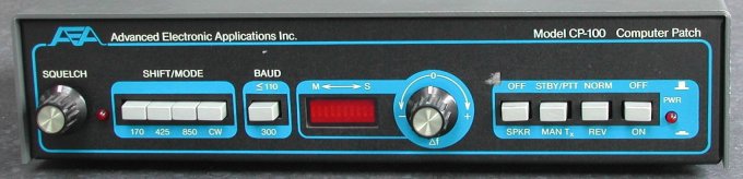
The demodulator
To be able to receive RTTY signals at all shifts and tones you must build a few more bandfilters
(read the backgrounder on RTTY signals). The center frequencies of the bandfilters are the following.

... to be continued ...
but this is a low-priority project. I have some other contraptions to finish first!
(A switchbox to connect two sets mutual exclusive to either a PC with galvanic isolation, or to a real handmike with PTT,
morse key and loudspeaker or headphones. This project will be publicized in "Electron", a monthly magazine for HAM radio amateurs).